

Center console structure of vehicle
- Summary
- Abstract
- Description
- Claims
- Application Information
AI Technical Summary
Benefits of technology
Problems solved by technology
Method used
Image

Examples
Embodiment Construction
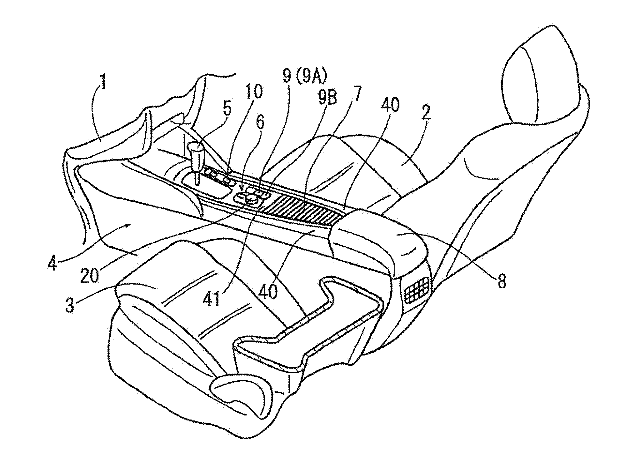
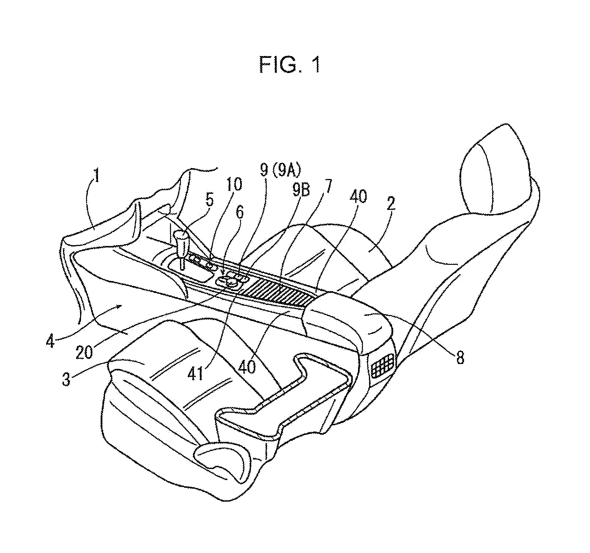
[0021]In FIG. 1 showing front row seats and its surroundings of a vehicle, the reference numeral 1 denotes an instrument panel (only a part of its middle portion in a vehicle width direction is shown), the reference numeral 2 denotes a driver's seat, and the reference numeral 3 denotes a front passenger's seat. The vehicle shown in FIG. 1 has the steering wheel on the right side.
[0022]A center console including a console main body 4 extending in a front-rear direction of the vehicle is provided on a vehicle floor between the driver's seat 2 and the front passenger's seat 3. The front end of the console main body 4 is connected to a widthwise middle portion of the instrument panel 1.
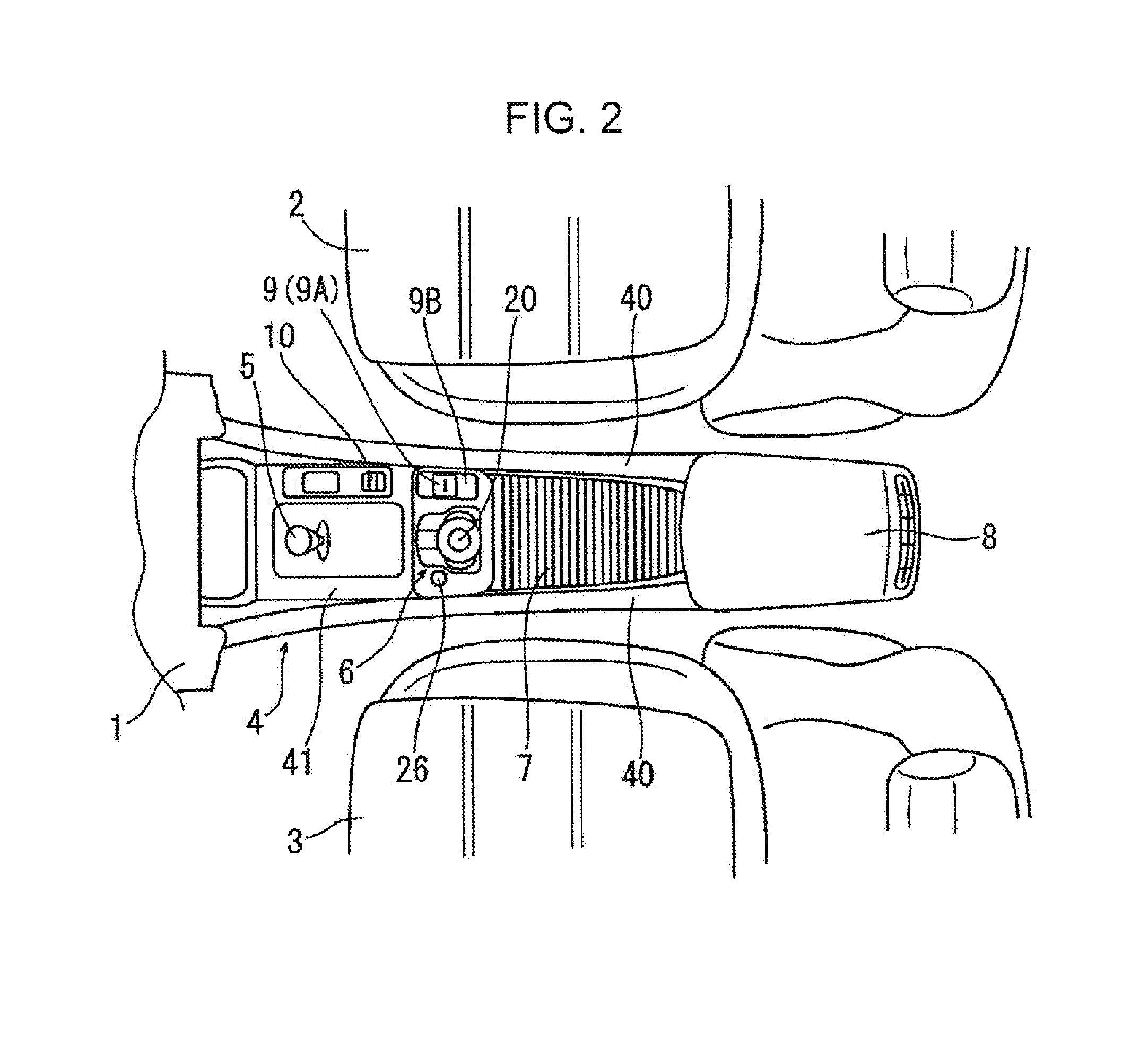
[0023]On the top surface of the console main body 4 are disposed an operation knob 5 for operating a transmission, a switch device 6, a lid member 7, and an armrest 8 in the order from front to rear. Further, on the side (right side) of the top surface of the console main body 4 that is closer to the driv...
PUM
 Abstract
Description
Claims
Application Information