
System and method for monitoring an electrical network

a technology of electrical network and monitoring system, applied in the direction of power supply testing, instruments, electric devices, etc., can solve the problems of limited analysis of data generated by such systems, and bulky prior art devices

Inactive Publication Date: 2015-12-10
CIRCUITMETER
View PDF10 Cites 94 Cited by
  • Summary
  • Abstract
  • Description
  • Claims
  • Application Information

AI Technical Summary

Benefits of technology

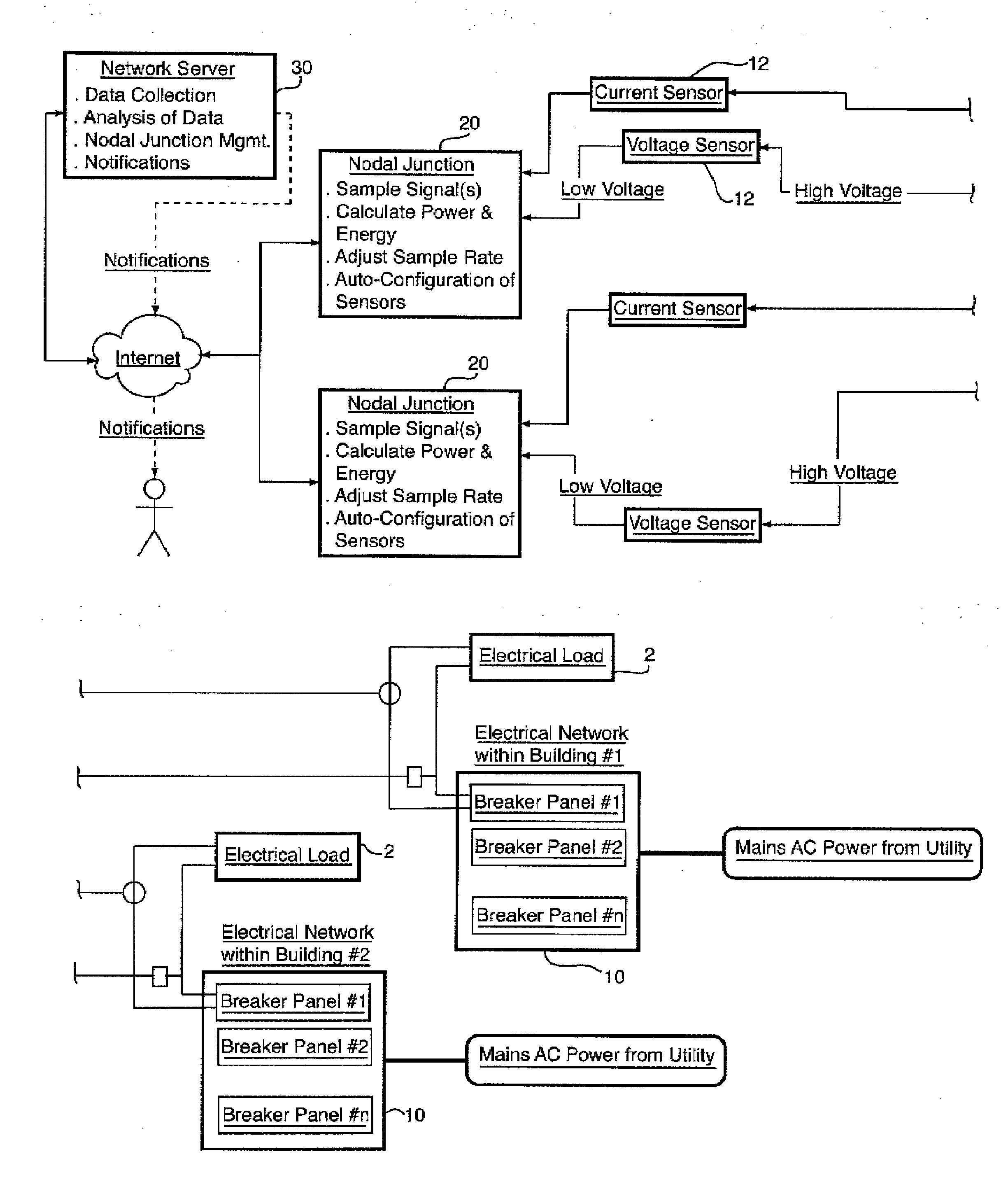
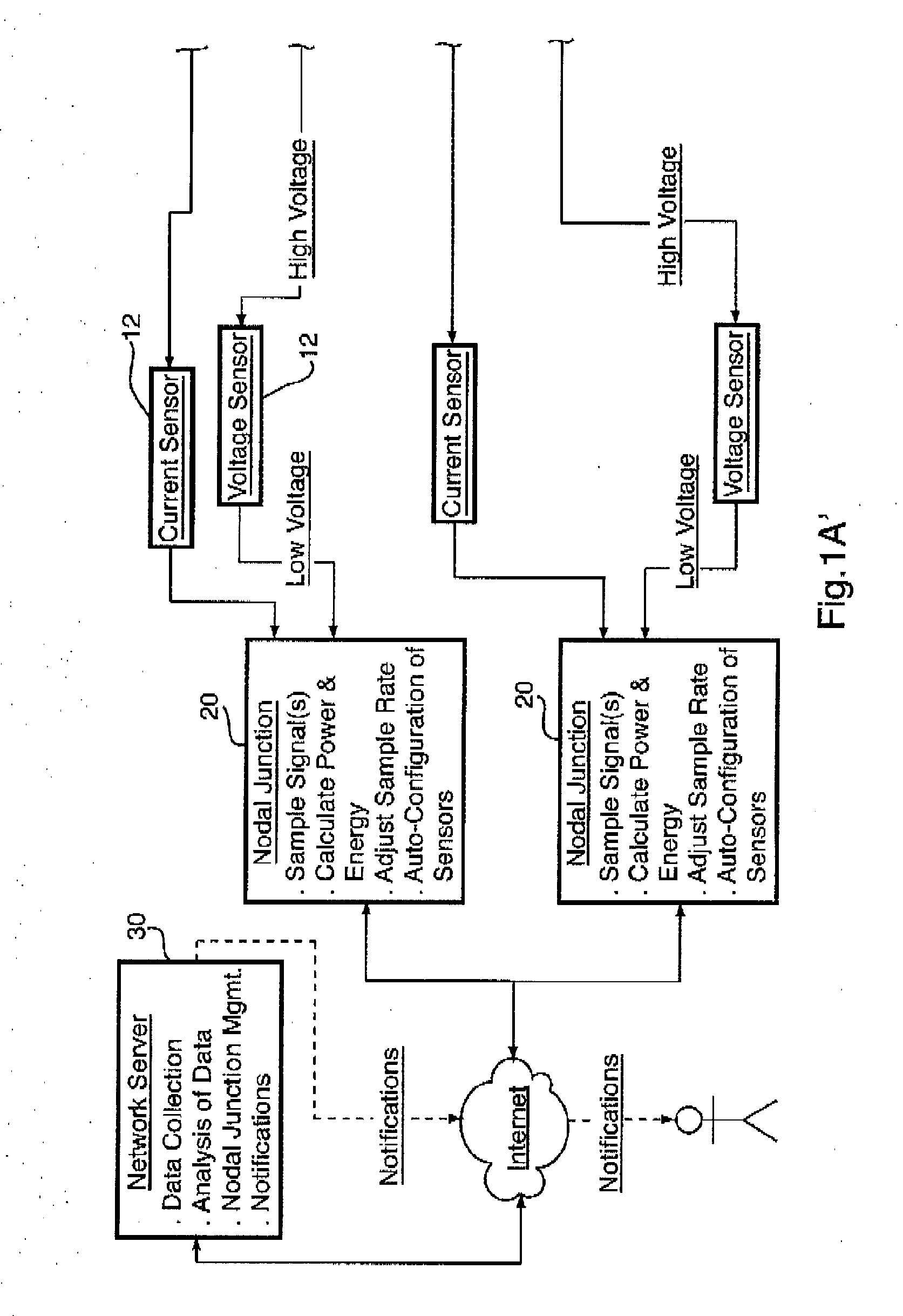
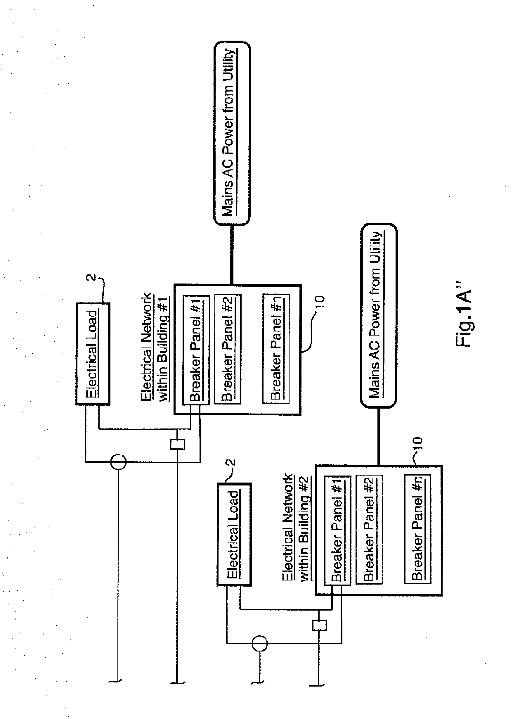
The invention is a system and method for monitoring the electrical energy usage of loads connected to an electrical network. The system includes sensors that measure the electrical energy consumed by the loads, a nodal junction that calculates various electrical measurements, and a network communication circuit that securely transmits the data to a network server. The system can also analyze the data and provide valuable insights into the usage patterns of the loads. The invention overcomes limitations of previous energy monitoring systems by being more versatile, safe, and secure.

Problems solved by technology

These prior art devices are bulky, expensive and tend to be limited with respect to the number of loads that can be monitored by a single device, frequently requiring considerable expertise in their implementation and use.
Many of these prior art devices are only able to measure just total electrical energy, total gas or total water consumed at the premises.
The analysis of data generated by such systems is also limited.
Different organizations and institutions can use energy-related information for disparate purposes, and conventional interfaces do not readily lend themselves to optimal data utilization by customers.

Method used


Image

  • System and method for monitoring an electrical network
  • System and method for monitoring an electrical network
  • System and method for monitoring an electrical network

Examples


Embodiment Construction

[0016]The various embodiments of the system of the invention address one or more of the above disadvantages and provide a versatile, safe and secure method of collecting, transferring and displaying electrical supply and usage data and parameters derived from the data. It will be appreciated that not every advantage of the invention applies to every embodiment described herein.

[0017]The invention thus provides a system for monitoring electrical variables of at least one AC electrical load wired to at least one breaker pole connected to a phase of an AC electrical source, comprising at least one ampere sensor configured to produce an output analog signal proportional to the amperes in at least one electrical load conductor, comprising an inductor having at least one complete electrical turn in inductive communication with said load conductor, at least one nodal junction configured to calculate at least one electrical measurement from the signal received from the at least one sensor, ...


PUM


Abstract

An energy monitoring system which in preferred embodiments employs at least one nodal junction receiving and creating data by analog to digital conversion from a plurality of local node sensors. Data accumulated by the nodal junction is used for analysis of wave patterns to detect anomalies in the local electrical network and / or loads connected to the local electrical network. Anomalies can be detected in various ways, including: comparison of data with historical data acquired from the local node sensors; comparison of data with known wave pattern profiles for similar loads; and comparison of data with data acquired from local node sensors at other locations. Thus, the accumulation of data in the system of the invention provides the ability to perform comparative analysis to a baseline or standard, and also the ability to perform comparative analysis at an enterprise level across different target locations.

Description

FIELD OF THE INVENTION[0001]This invention relates to an energy monitoring systems for measuring and recording the electrical energy consumed by one or more loads.BACKGROUND OF THE INVENTION[0002]It is well known in the art that devices can be made to measure and record the electrical energy used by a load and some of these devices with further enhancements can be made to measure and record the current harmonics created by the load. There are a number of patents which reveal devices which can measure the energy consumption and current harmonics of loads, both individual and grouped. These prior art devices are bulky, expensive and tend to be limited with respect to the number of loads that can be monitored by a single device, frequently requiring considerable expertise in their implementation and use. Many of these prior art devices are only able to measure just total electrical energy, total gas or total water consumed at the premises.[0003]The analysis of data generated by such sy...

Claims


Application Information

Patent Timeline
IPC IPC(8): G01R21/133G01R31/42
CPCG01R31/42G01R21/133G01R19/2513G01R22/10
Inventor ORDANIS, MICHAEL
Owner CIRCUITMETER
Learn More