Touch panel

a technology of touch panel and conductive element, which is applied in the field of touch panel, can solve the problems of poor protection poor protection of the environment or other processes, and affect the sidewalls of the middle-layer conductive element of the bonding pad, etc., and achieves the effect of being easily damaged by the environment or other

Active Publication Date: 2015-12-10
TPK TOUCH SOLUTIONS (XIAMEN) INC
View PDF17 Cites 10 Cited by
  • Summary
  • Abstract
  • Description
  • Claims
  • Application Information

AI Technical Summary

Benefits of technology

[0007]The disclosure provides touch panels which can overcome the above-mentioned problems of conventional touch panels. According to embodiments of the disclosure, a protection component is disposed at least at the sides of the bonding pads. Therefore, the above-mentioned problems of the sides of the bonding pads of the conventional touch panels being easily damaged by the environment or other processes are overcome.
[0009]According to the embodiments of the disclosure, at least the first long side and the second long side of the bonding pad are covered by the protection component. Thus, the sides of the bonding pads of the touch panels easily damaged by the environment or other processes are overcome. The bonding quality of the bonding pads with the flexible printed circuit board is enhanced and thus the reliability of the touch panel is also enhanced.

Problems solved by technology

However, the materials of better conductivity usually provide poor protection against the environment or other processes.
Although the upper surface and the lower surface of the middle-layered conductive element of the bonding pad are protected by the other conductive elements, the sidewalls of the middle-layered conductive element of the bonding pad are not protected by any protection element and may be affected by the environment, for example oxidation or other processes, through for example a process using an acid solution, a basic solution, or a cleaning liquid.
As a result, the conductive quality between the bonding pads of the touch panel and the flexible printed circuit board is poor and the reliability of the touch panel is thereby reduced.

Method used


Image

  • Touch panel
  • Touch panel
  • Touch panel

Examples


Embodiment Construction

[0026]The following description is of the best-contemplated mode of carrying out the invention. This description is made for the purpose of illustrating the general principles of the invention and should not be taken in a limiting sense. The scope of the invention is best determined by reference to the appended claims.

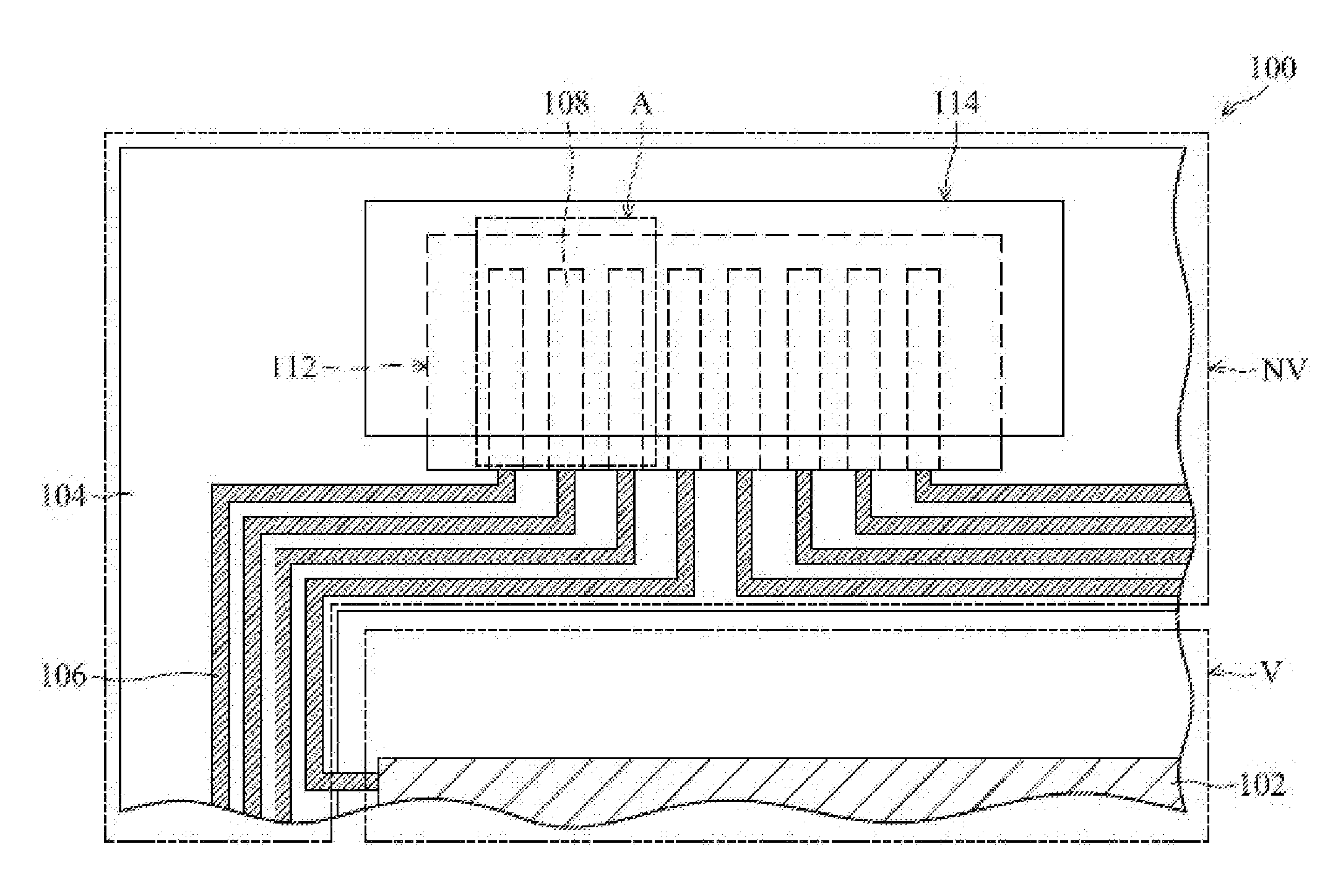
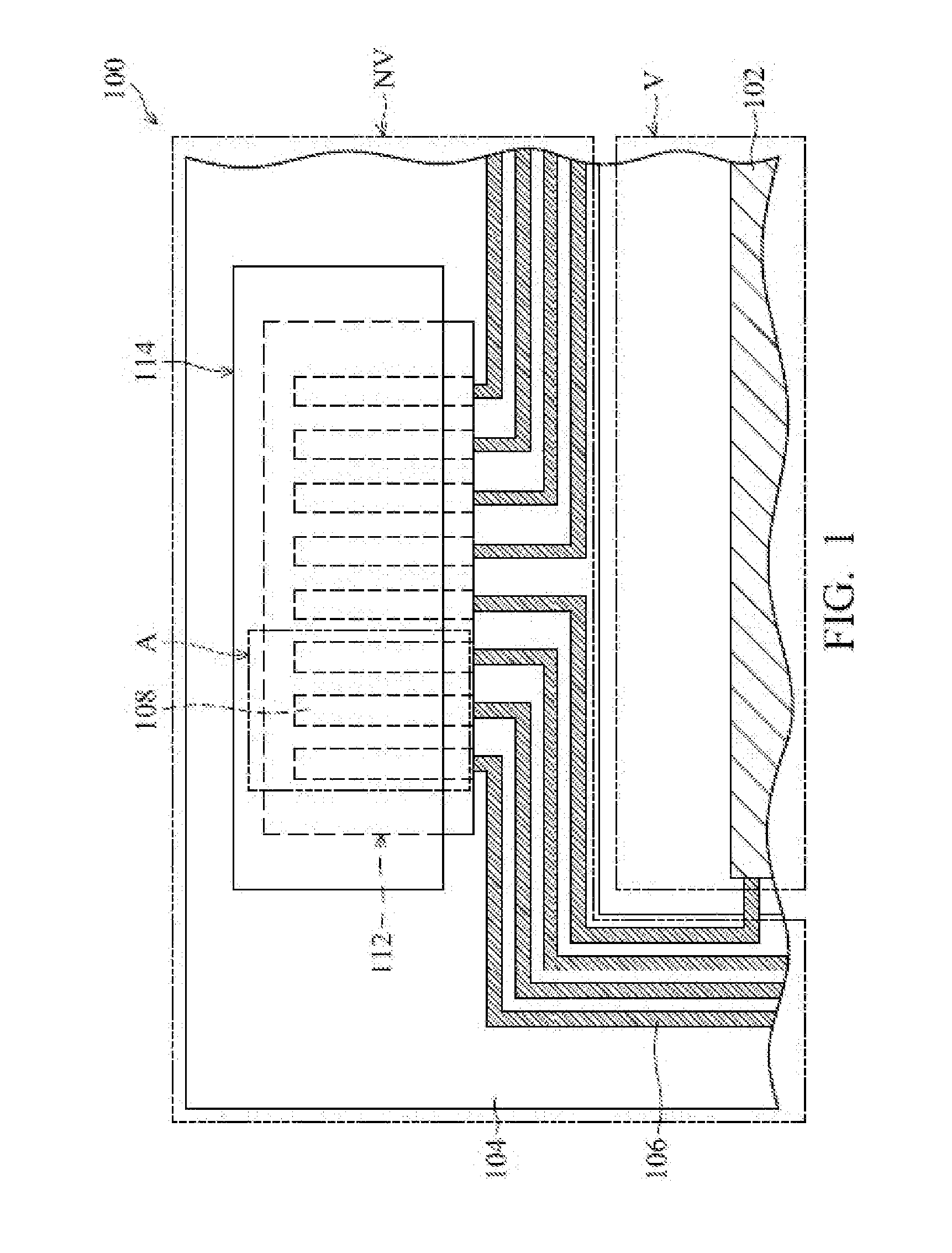
[0027]In the accompanying drawings, in order to clearly illustrate the characteristics of embodiments of the invention, each element in the touch panels may not be drawn to scale. Moreover, in the descriptions that follow, the orientations of “on”, “over”, “above”, “under” and “below” are used for representing a direction of a cover lens 101 of the touch panel disposed at the underside, except for FIG. 9. The orientations are only used for representing the relationship between the relative positions of each element in the touch panel. However, in an actual application of the touch panel, the cover lens 101 is disposed at the top of the touch panel for users.
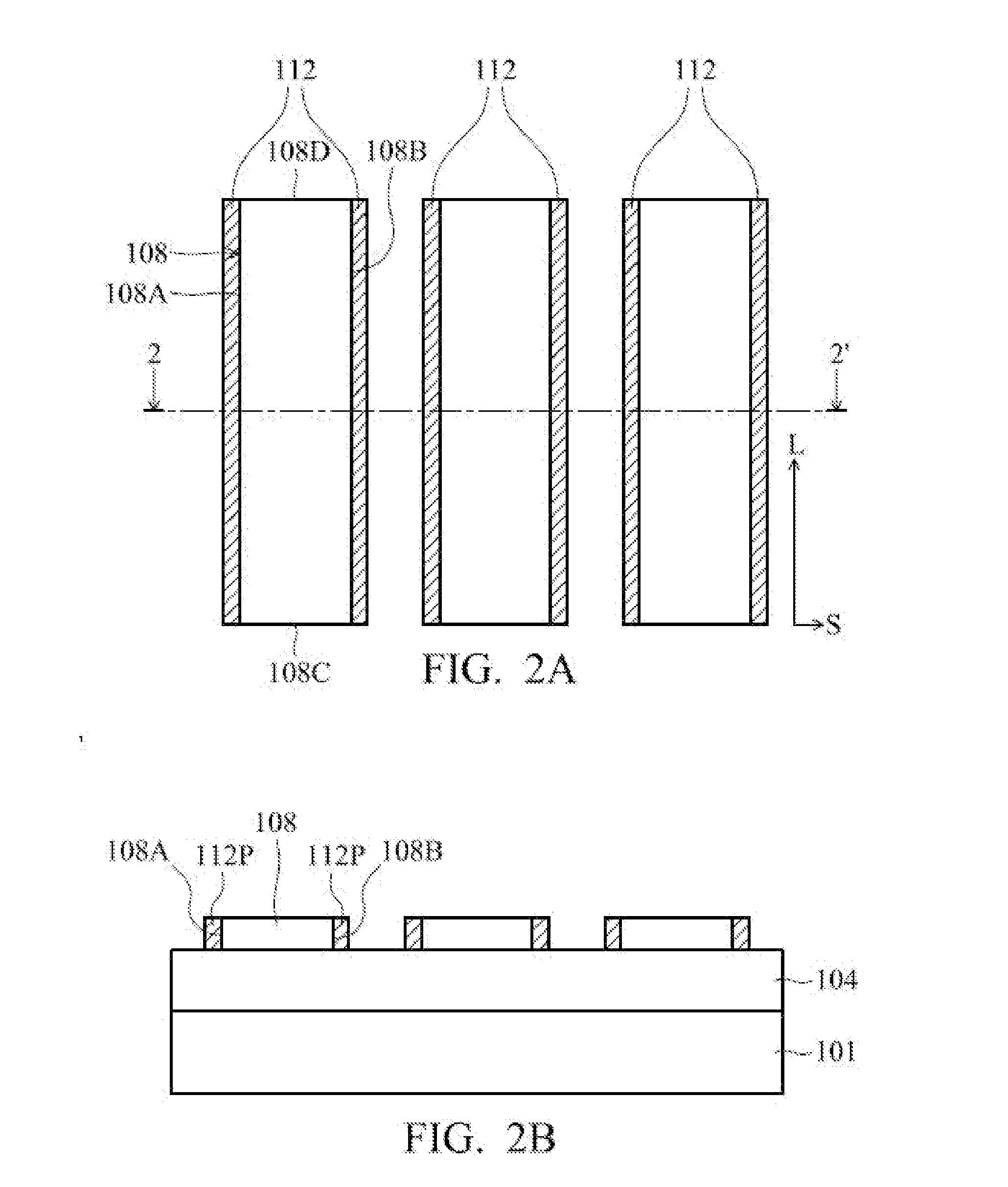
[0028]Refer...


PUM


Abstract

A touch panel is provided. The touch panel includes at least a bonding pad, a touch-sensing structure and at least a protection component. The bonding pad has a first long side, a first short side, a second long side, and a second short side. The first long side is adjacent to the first short side and the second short side, and the first long side is opposite to the second long side. A touch-sensing structure is electrically connected to the first short side of the bonding pad. The protection component is disposed at the first long side and the second long side.

Description

[0001]This Application claims priority of the People's Republic of China Patent Application No. 201310228299.1, filed on Jun. 8, 2013, the entirety of which is incorporated by reference herein.BACKGROUND OF THE INVENTION[0002]1. Field of the Invention[0003]The present disclosure relates to touch technology, and in particular, relates to a touch panel.[0004]2. Description of the Related Art[0005]Recently, touch panel techniques have been developed to be a main input interface and have been popularly applied in various electronic products, such as mobile phones, personal digital assistants (PDA), and handheld personal computers. Touch-sensing elements of the touch panel are electrically connected to bonding pads through wires and the bonding pads are bonded with a flexible printed circuit board. Therefore, sensing-signals of the touch-sensing elements can be conveyed to an exterior processor for performing a treatment of the sensing-signals.[0006]In general, the touch-sensing elements...

Claims


Application Information

Patent Timeline
Patent Type & Authority Applications(United States)
IPC IPC(8): G06F3/044
CPCG06F3/044G06F3/04164G06F1/16G06F2203/04103G06F2203/04111H01L24/06H03K17/962
Inventor LIN, YALUYU, JINGSU, YUNCONGHUANG, LI
Owner TPK TOUCH SOLUTIONS (XIAMEN) INC
Why Eureka
Try Eureka