Mounting frame for an electrically driven motor vehicle

a motor vehicle and mounting frame technology, applied in the direction of superstructure, battery/cell propulsion, understructure, etc., can solve the problems of reducing the stability of the motor vehicle supporting frame, no contribution to passive safety, and the mounting cradle and the electric control unit do not increase the stability of the mounting frame, so as to improve the formation of blocks, reduce the weight of the adaptation element, and improve the effect of deformation energy absorbing efficiency

Active Publication Date: 2015-12-17
DR ING H C F PORSCHE AG
View PDF4 Cites 8 Cited by
  • Summary
  • Abstract
  • Description
  • Claims
  • Application Information

AI Technical Summary

Benefits of technology

[0010]The longitudinal beams form a frame arrangement that is open outward in the longitudinal direction or toward an end of the motor vehicle. Thus, the mounting frame can be produced with little technical outlay. The hollow body and the electric drive unit are connected fixedly to the two frame beams to form the closed frame section and hence function to stiffen the mounting frame in general. More particularly, the longitudinal beams, the hollow body and the electric drive unit form a block that increases the mechanical rigidity of the mounting frame. The electric drive unit and the hollow body form a stable unit together with the longitudinal beams. Thus, the mounting frame can ensure the required passive safety and controlled deformation behavior in the event of a collision of the electrically driven motor vehicle despite the absence of massive components of an internal combustion engine drivetrain.
[0023]The hollow body may be a closed hollow body. In this way, the mechanical stiffness of the hollow body can be increased, and any electrical component arranged in the hollow body can be fully enclosed and protected.

Problems solved by technology

Thus, the mounting cradle and the electric control unit do not increase the stability of the mounting frame in general and make no contribution to passive safety.
The absence of components of an internal combustion engine and / or a transmission unit in an electric motor vehicle reduces the stability of the motor vehicle supporting frame, and additional stiffening means are required to ensure passive safety for the occupants in the event of the motor vehicle being involved in a collision.

Method used


Image

  • Mounting frame for an electrically driven motor vehicle
  • Mounting frame for an electrically driven motor vehicle
  • Mounting frame for an electrically driven motor vehicle

Examples


Embodiment Construction

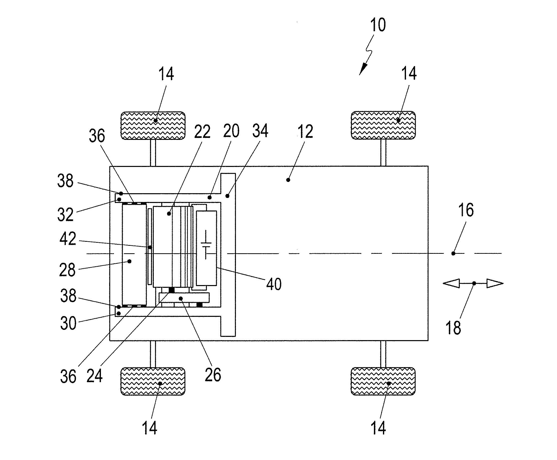
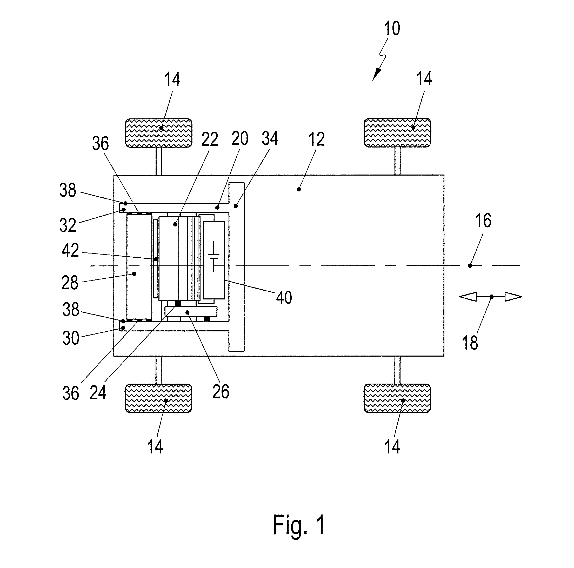
[0029]An electrically driven motor vehicle is illustrated schematically in FIG. 1 and is denoted as a whole by 10. The motor vehicle 10 has a supporting frame 12 on which wheels 14 of the motor vehicle 10 are mounted. The motor vehicle 10 generally has a longitudinal axis 16 and moves substantially in a longitudinal direction parallel to the longitudinal axis 16, as indicated by an arrow 18.

[0030]A mounting frame 20 is fixed to the supporting frame 12 for mounting electric drive components of the motor vehicle 10. An electric drive machine 22 is mounted on the mounting frame 20 and a shaft 24 of the drive machine 22 is connected to the wheels via a transmission 26 to drive the motor vehicle 10. A stiffening element 28 in the form of a hollow body also is mounted on the mounting frame 20. An electrical component of the electrically driven motor vehicle 10 may be accommodated in the hollow body 28 to reinforce the stiffening element 28 mechanically and to utilize the structural space ...


PUM


Abstract

A mounting frame (20) for an electrically driven motor vehicle (10) has two longitudinal beams (30, 32) oriented in a longitudinal direction (18) of the motor vehicle (10). An electric drive unit (22) for driving the motor vehicle (10) is mounted on the longitudinal beams (30, 32). The longitudinal beams (30, 32) form a frame arrangement that is open out in the longitudinal direction (18). A flexurally stiff hollow body (28) is formed separately from the longitudinal beams (30, 32) and is fixed to the mounting frame (20). The hollow body (28) is arranged between the longitudinal beams (30, 32) and is mechanically fixedly connected to the longitudinal beams (30, 32) to form a closed frame section.

Description

CROSS REFERENCE TO RELATED APPLICATION[0001]This application claims priority under 35 USC 119 to German Patent Appl. No. 10 2013 106 141.9 filed on Jun. 13, 2013, the entire disclosure of which is incorporated herein by reference.BACKGROUND[0002]1. Field of the Invention[0003]The invention relates to a mounting frame for an electrically driven motor vehicle having two longitudinal beams that are oriented in a longitudinal direction of the motor vehicle. An electric drive unit for driving the motor vehicle is mounted on the longitudinal beams. The longitudinal beams form a frame arrangement that is open out in the longitudinal direction. A flexurally stiff hollow body is formed separately from the longitudinal beams and is fixed to the mounting frame.[0004]2. Description of the Related Art[0005]US 2004 / 0090085 discloses a mounting frames for fixedly mounting drive components of an electrically driven motor vehicle on a supporting frame or a chassis of the motor vehicle. The mounting ...

Claims


Application Information

Patent Timeline
Patent Type & Authority Applications(United States)
IPC IPC(8): B60K1/00B62D21/17
CPCB62D21/17B60K1/00B60K1/04B60K2001/001B60K2001/0438B62D21/11B62D25/082B60L50/66Y02T10/70B60L2200/00B60Y2200/91B62D21/152B60K5/1216B60K17/12
Inventor MERKEL, TIMO FABIAN
Owner DR ING H C F PORSCHE AG
Why Eureka
Try Eureka