Vane pump with adjustable delivery volume

a technology of a vane and a delivery volume, which is applied in the direction of liquid fuel engines, machines/engines, rotary piston liquid engines, etc., can solve the problems of cost-related measures and achieve the effect of more economical

Active Publication Date: 2017-02-16
PUMP TECH SOLUTIONS PS GMBH
View PDF2 Cites 0 Cited by
  • Summary
  • Abstract
  • Description
  • Claims
  • Application Information

AI Technical Summary

Benefits of technology

[0012]Accordingly, it is advantageous if at least one of the two control ducts is arranged in the pump housing or in a cover of the housing, such that the control ducts cross without coming into contact with one another. Here, both control ducts can also be implemented in the material of the pump housing or cover, in the form of bores which do not touch one another but only cross. The control ducts are preferably implemented in the cover, which means that the pump housing itself does not have to be changed or adapted. In particular, the installation area for the control device and the design of the control device itself can remain unchange

Problems solved by technology

Usually, these complicated and costly measures are carried out, which results in the kit for a left-rot

Method used


Image

  • Vane pump with adjustable delivery volume
  • Vane pump with adjustable delivery volume
  • Vane pump with adjustable delivery volume

Examples


Embodiment Construction

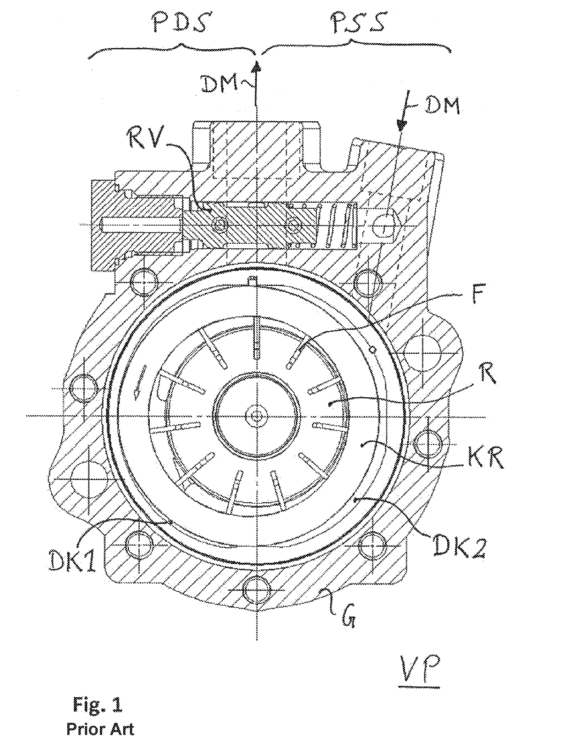
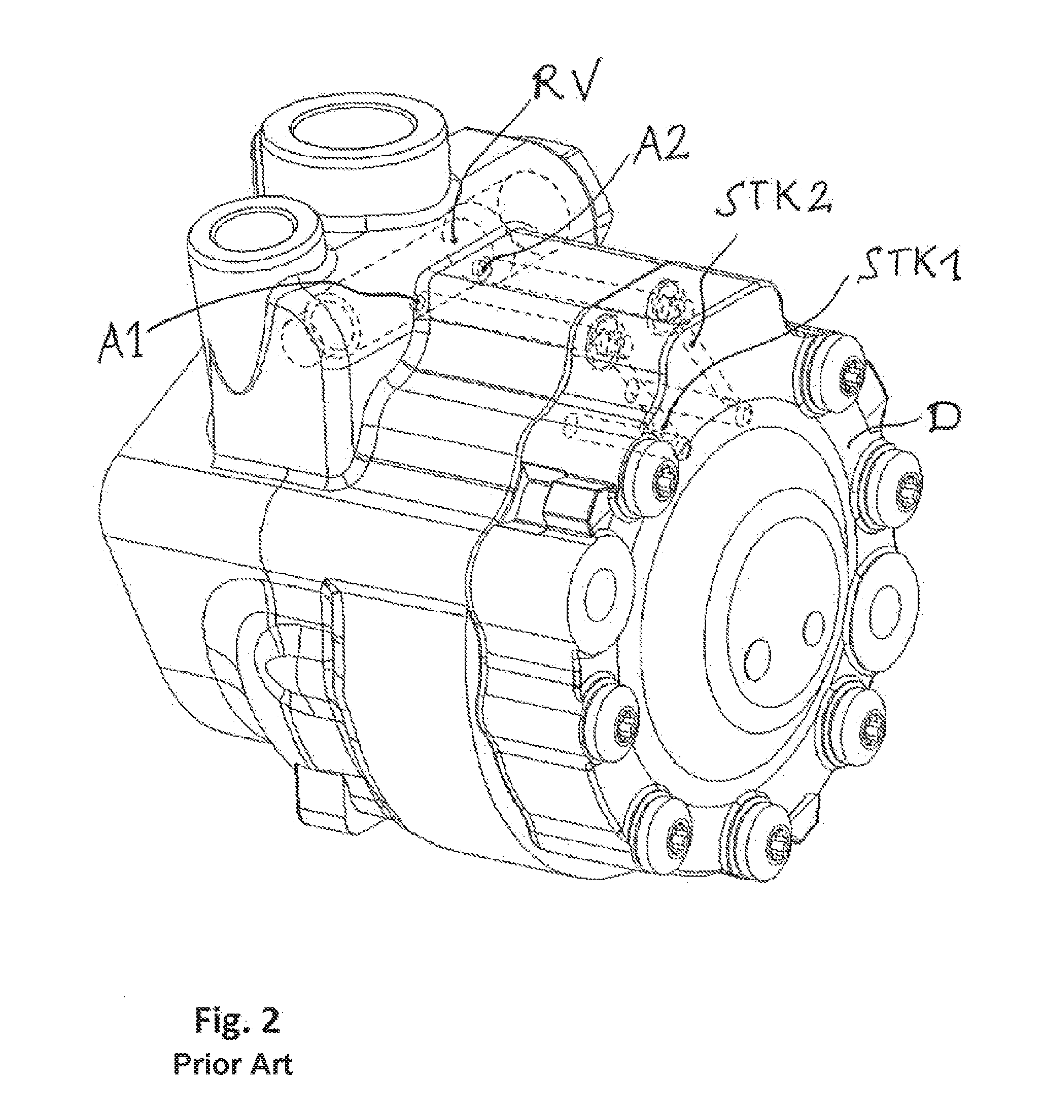
[0023]Starting from FIGS. 1 to 3, the vane pump VP according to the invention also has a pump housing G, in which a rotor R is arranged within a cam ring KR, which in turn can be displaced via pressure chambers DK1 and DK2 such that the eccentricity of the cam ring KR relative to the rotor R required for the desired delivery volume is set.

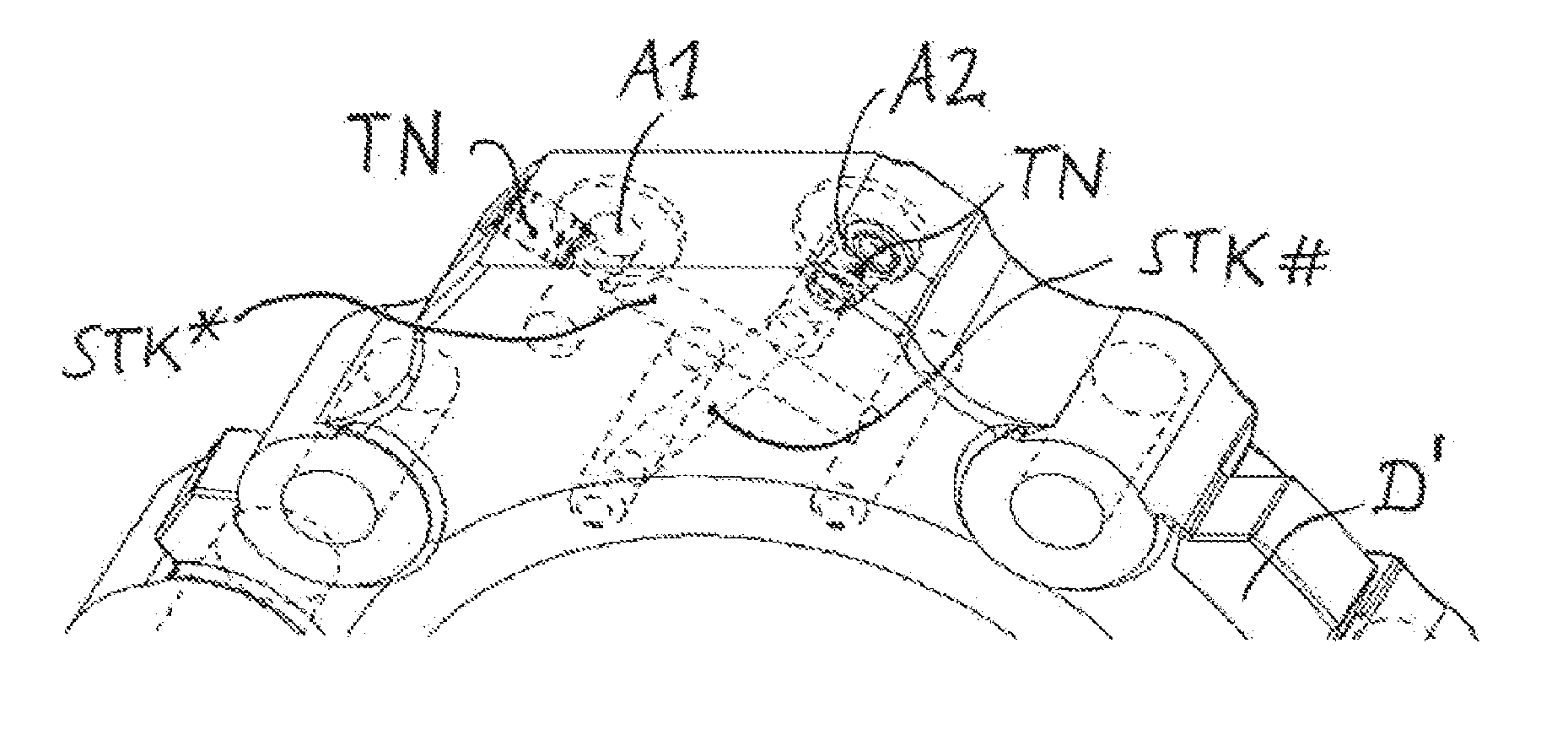
[0024]For a left-rotating configuration of the pump, the structure shown in FIGS. 1 to 3 is suitable. In conjunction with the kit according to the invention, the cover D shown in FIG. 4a, which has two control ducts STK1 and STK2 running in parallel, is now used, so that initially the pressure chambers are still connected as usual to the control device (valve RV in FIGS. 1-3). In order to reconfigure the pump to right-hand rotation, the cover D is replaced by a cover D′, which is shown in FIG. 4b. This cover D′ has two criss-crossing control ducts STK* and STK#, which are implemented by means of appropriate bores, un-needed openings being closed by...


PUM


Abstract

The invention proposes a vane pump (VP) with adjustable delivery volume, which vane pump has a pump housing (G), a cam ring (KR) arranged therein, and a rotor (R) which is rotatably movably mounted therein. The vane pump (VP) has a regulating device (RV) through which the delivered pressure medium (DM) flows and which has two outlets (A1, A2) which are each connected to one of two pressure chambers (DK1, DK2) in order to charge these with regulable proportions of the pressure medium (DM), wherein, to change the eccentricity of the cam ring (KR) relative to the rotor (R), the two pressure chambers (DK1, DK2) act on the outer surface of the cam ring (KR). The vane pump (VP) has two criss-crossing control ducts (STK*, STK#) which connect in each case one of the outlets (A1, A2) to one of the two pressure chambers (DK1, DK2) in order to charge these with the regulable proportions of the pressure medium (DM). The criss-crossing control ducts (STK*, STK#) are preferably arranged in a cover (D′) of the pump housing such that the control ducts (STK*, STK#) are in a criss-crossing arrangement without coming into contact with one another. By means of this design, the vane pump (VP) can be easily reconfigured for a change in rotational direction of the rotor.

Description

BACKGROUND OF THE INVENTION[0001]The invention relates to a vane pump. In particular, the invention relates to a vane pump for use in a power steering system.[0002]Usually, vane pumps with adjustable delivery volume, which are frequently also designated as adjustable pumps, are designed as follows: In essence, a cam ring or stroke contour ring and a rotatably movably mounted rotor are arranged in a pump housing. The rotor has radial slots, in which vanes are arranged such that they can be displaced radially and guided positively by the slots. During operation of the vane pump, the vanes thus slide along with their outer ends resting on the inner wall of the cam ring and, as a result, effect the delivery of a pressure medium (e.g. pressurized oil). As distinct from pumps with a constant delivery volume (constant delivery pumps), pumps with variable delivery volume are able to avoid the situation in which, in particular at high rotational speeds, overproduction of pressurized oil resu...

Claims


Application Information

Patent Timeline
IPC IPC(8): F04C14/22F04C14/04F04C2/344
CPCF04C14/223F04C2/344B62D5/14F04C2240/20F04C2240/10F04C14/04F01C21/108F04C14/226F04C2240/70
Inventor BURDIAK, JOHANNESVOGT, RICHARDZELLNER, UWE
Owner PUMP TECH SOLUTIONS PS GMBH
Why Eureka
Try Eureka