Method and device for checking an electrical value of an electric machine

a technology of electrical value and electric machine, which is applied in the direction of mechanical measurement arrangement, mechanical instruments, and mechanical means, etc., can solve the problems of inability to reliably measure the torque, the three phase current transformation is required for the three phase current to be technically complex, and the motor current measurement is possibl

Active Publication Date: 2022-11-01
CARL ZEISS IND MESSTECHN GMBH
View PDF14 Cites 0 Cited by
  • Summary
  • Abstract
  • Description
  • Claims
  • Application Information

AI Technical Summary

Benefits of technology

[0019]The drive current, which is fed to the electric drive for the purpose of driving the rotor, is detected by the method according to the invention and the apparatus according to the invention for checking an electrical variable of the electric machine and the electrical input variable is calculated on the basis of the detected drive current and an observation of the electrical power consumed by the electric machine, with the result that the measured drive current can be confirmed by comparing the calculated value of the electrical input variable with the measurement value of the electrical input variable. The drive current can be checked metrologically by way of said comparison of the measured electrical input variable and the electrical input variable calculated on the basis of the drive current, with the result that additional redundancy can be provided with little technical outlay and the reliability of the motor current measurement can be increased thereby. The drive current is detected with a certain factor of uncertainty by the method according to the invention and the apparatus according to the invention and can be checked by the theoretical performance observation and the measurement of the electrical input variable by a second measurement value, with the result that the measured value of the drive current can be confirmed with little technical outlay.
[0053]Overall, reliable checking of the measurement of the drive current can be carried out by the present invention with little technical outlay, wherein the thus measured and checked drive current can be supplied to a central control unit with little technical outlay, since the checking takes places separately from the measurement of the drive current and the electrical input variable can be detected externally at the electrical power supply of the electric machine. The different electrical energies in the form of an energy conservation observation can be taken into account by means of the performance model and the physical variables of the individual energy components can be determined separately, with the result that the electrical input variable can be precisely calculated as reference.

Problems solved by technology

The motor current of DC motors is usually detected by a shunt resistor in the motor line or by a Hall sensor and can additionally be redundantly detected in the central controller, with the result that redundant motor current measurement is possible with little outlay.
In this case, however, a technically complex transformation of the three phase currents is required for determining the torque.
Since the detection of the effective motor current is technically complex and complicated in the case of the multi-phase electrically commutated DC machines, most drives of this kind do not involve redundant detection of the motor current, with the result that correspondingly reliable measurement is not possible for safety-relevant applications.
For safe motor control, however, the detected motor currents have to be reliably transmitted to the central controller by means of the digital bus system, with the result that the transmission of the measurement value of the motor current to the central controller is generally associated with a high technical outlay.

Method used


Image

  • Method and device for checking an electrical value of an electric machine
  • Method and device for checking an electrical value of an electric machine
  • Method and device for checking an electrical value of an electric machine

Examples


Embodiment Construction

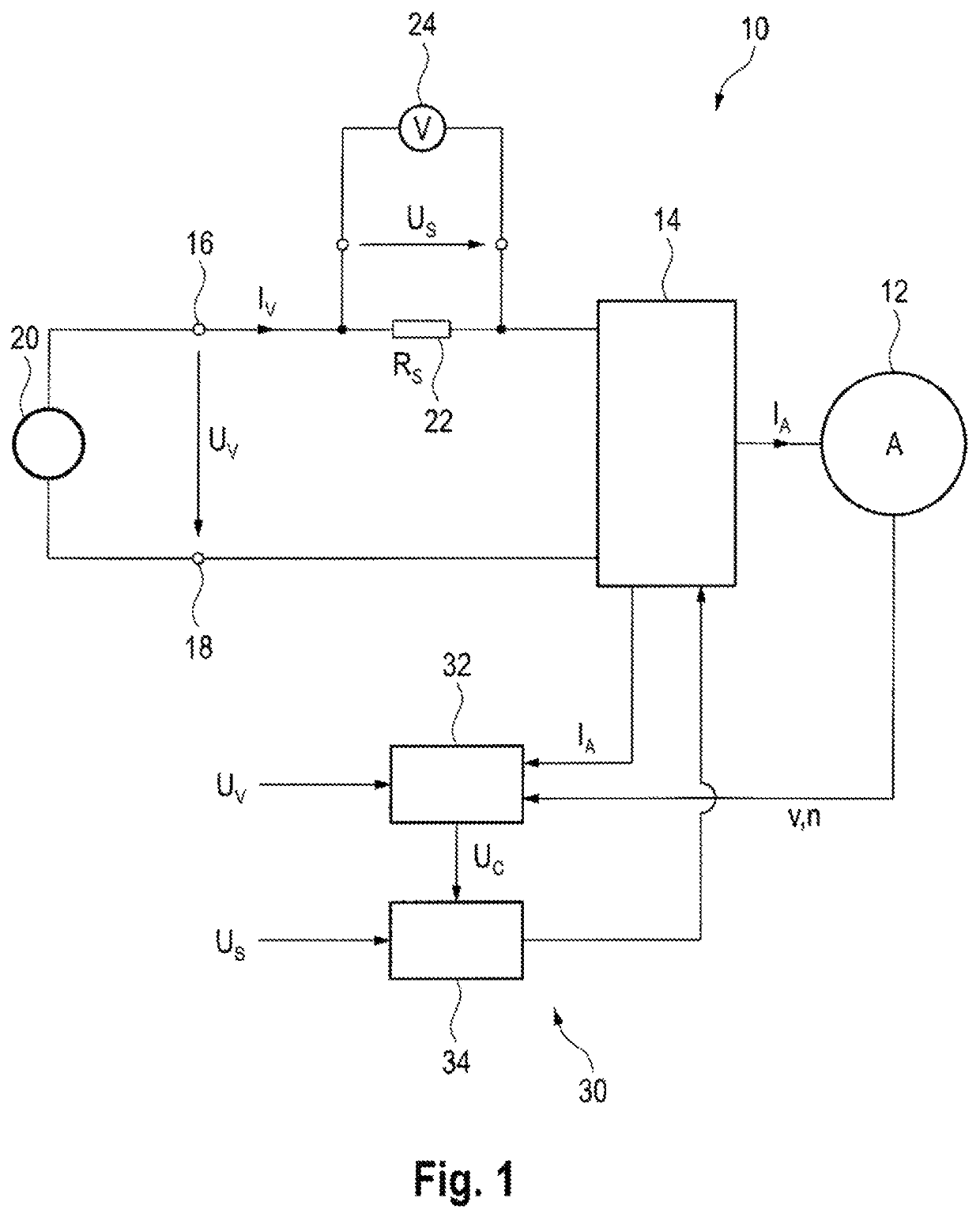
[0060]FIG. 1 schematically illustrates an electric machine, which is generally denoted by 10. The electric machine 10 has an electric drive 12 and a control unit 14 for actuating or for energizing the electric drive 12. The electric drive 12 can generally be configured as a rotary motor or as a linear motor and generally has a fixed stator and a moving rotor, wherein, depending on the embodiment, the rotor provides a torque or a linear motor force. The control unit 14 is electrically connected to the stator of the electric drive 12 and actuates the electric drive 12 or energizes the electric drive 12 by means of a motor current IA. The torque provided by the rotor or the motor force provided by the rotor is proportional to the motor current IA, with the result that the torque or the motor force can be controlled or limited accordingly by way of the motor current IA.

[0061]The control unit 14 is connected to electrical input connections 16, 18 of the electric machine 10 in order to el...


PUM


Abstract

The invention relates to a method for checking an electrical value of an electric machine, in particular an electric machine of a coordinate measuring device. The electric machine has an electric drive comprising a stator and a rotor. The method includes the steps of: detecting a value of a drive current delivered to the electric drive for driving the rotor, detecting a measured value of an electrical input variable of the electric machine, determining a calculated value of the electrical input variable on the basis of the detected value of the drive current and on the basis of a performance model of the electric machine, and determining a comparison value on the basis of the detected measured value and the calculated value of the electrical input variable, in order to check the detected value of the drive current.

Description

CROSS-REFERENCES TO RELATED APPLICATIONS[0001]This application is a continuation of international patent application PCT / EP2016 / 061669 filed on May 24, 2016 designating the U.S., which international patent application claims priority from German patent application DE 10 2015 110 174.2 filed on Jun. 24, 2015. The entire contents of these priority applications are incorporated herein by reference.BACKGROUND OF THE INVENTION[0002]The present invention relates to a method for checking an electrical variable of an electric machine, in particular an electric machine of a coordinate measuring machine, wherein the electric machine has an electric drive having a stator and a rotor.[0003]The invention further relates to an apparatus for checking an electrical variable of an electric machine, in particular an electric machine of a coordinate measuring machine, wherein the electric machine has an electric drive having a stator and a rotor.[0004]The present invention further relates to a method ...

Claims


Application Information

Patent Timeline
Patent Type & Authority Patents(United States)
IPC IPC(8): H02P6/12G01B5/008G01R21/133H02P6/08H02P29/024H02P23/00H02M1/00G01B21/04
CPCH02P6/12G01B5/008G01R21/133H02P6/08H02P23/0022H02P29/0241G01B21/047H02M1/0009
Inventor GRUPP, GUENTERRUCK, OTTOUHL, PETERMAIER, THOMAS
Owner CARL ZEISS IND MESSTECHN GMBH
Why Eureka
Try Eureka