
Cooking Container Lid Having Pyrolysis Function

a technology of pyrolysis and cooking container lid, which is applied in the field of cooking container lids having pyrolysis devices, can solve the problems of inability to solve the problem of diffusing fumes, the economic cost of re-installing the range hood, and the user's already affected by contaminants

Inactive Publication Date: 2015-12-24
LEE YOUNGHEE
View PDF9 Cites 30 Cited by
  • Summary
  • Abstract
  • Description
  • Claims
  • Application Information

AI Technical Summary

Benefits of technology

The cooking container lid described in this patent has a transparent glass body with a sealed edge to prevent any escape of steam or fumes. It also has a flow supply unit at the top that creates a vacuum to remove fumes and clean air. The lid is attached to a junction that covers the opening of the cooking container and protects the convection fan and other components from external impact. The bottom of the junction is attached to a durable metallic mesh cover. The technical effects of this inventive design include improved cooking efficiency, protection of components, and enhanced user experience.

Problems solved by technology

However, once the contaminants from cooking spread indoors, even after they are completely removed, the user has been already affected by the contaminants.
However, because the range hoods are located far from the place where the cooking is carried out, only a portion of the cooking fumes are discharged outside and the rest of the fumes are diffused into the kitchen.
Placing the range hoods close to the range can increase the efficiency for discharging out the fumes, but may also cause an economic cost for re-installing the range hood and violate the local building codes.
However, the above case adopts a method of re-heating the cooking cavity after taking out the food and cannot solve the problem of diffusing fumes during cooking.

Method used


Image

  • Cooking Container Lid Having Pyrolysis Function
  • Cooking Container Lid Having Pyrolysis Function
  • Cooking Container Lid Having Pyrolysis Function

Examples


Embodiment Construction

[0025]The objects and features of the present invention will be now made in detail to the preferred embodiment with reference to the attached drawings.

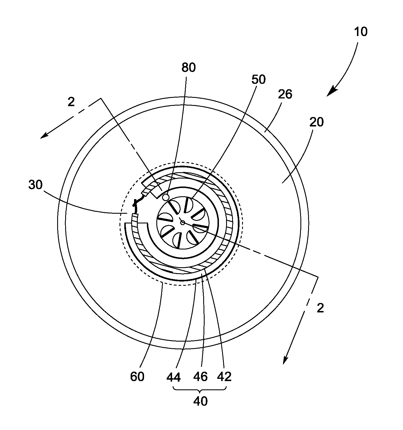
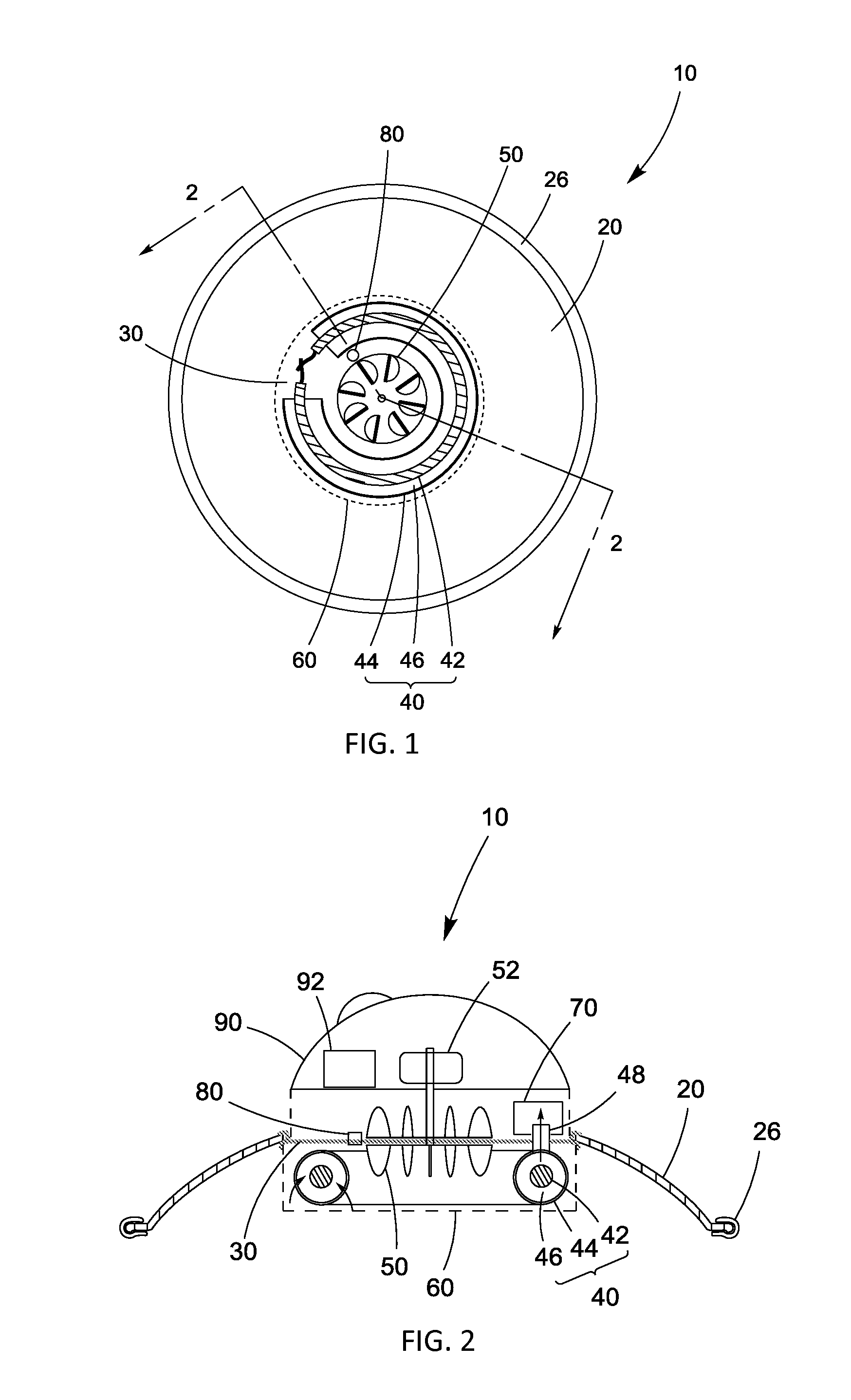
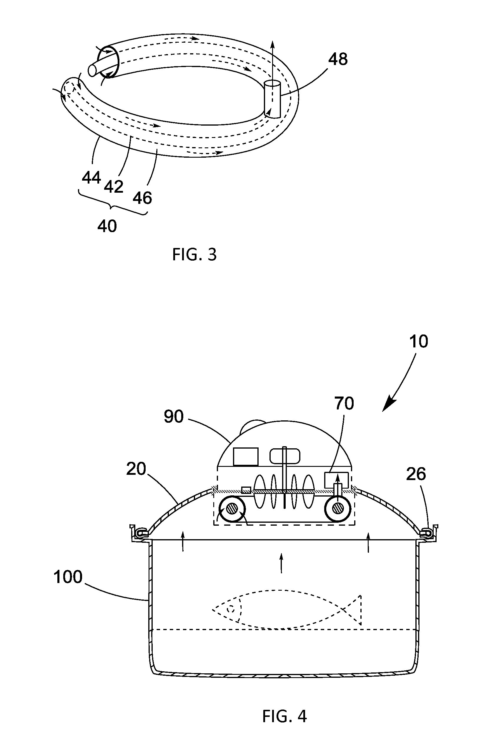
[0026]FIG. 1 is a front view showing a cooking container lid 10 where a portion of the mesh cover 60 is omitted and FIG. 2 is a sectional view taken along the line 2-2 of FIG. 1. As shown in FIG. 1 and FIG. 2, the lid body 20 has a round shape, and a round opening is formed at the center. It is desirable that the lid body 20 is made of heat and shatter-resistant transparent glass through which the inside of cooking container 100 (refer to FIG. 4) can be observed and has the shape of a round dome. The outer edge of the lid body 20 is wrapped by a packing seal 26. The packing seal 26 prevents any leakage of steam and fumes in the cooking container 100 through the gap between the lid body 20 and the opening of the cooking container 100. The packing seal 26 is made of silicone which can withstand the typical range of cooking temperature b...


PUM


Abstract

The cooking container lid having pyrolysis function comprises a lid body having an opening at the center and adapted to cover the upper part of a cooking container, a junction covering the opening of the lid body and attached to the lid body, a pyrolysis unit located at the bottom side of the junction and adapted to pyrolyze the fumes from cooking as well as to warm the food by radiating its heat towards the cooking container, a convection fan located at the junction and adapted to circulate air around the pyrolysis unit to force the heat effectively transferred to the food, a mesh cover attached to the junction to enclose the pyrolysis unit and the convection fan, an exhaust tube for connecting fluid communication with the pyrolysis unit and adapted to venting the steam and gas from the pyrolysis unit to the outside of the cooking container. The cooking container lid can keep the user safe by removing harmful fumes as soon as they are generated during cooking.

Description

FIELD OF THE INVENTION[0001]The present invention relates to a pyrolysis device for effectively removing volatile compounds and smells during cooking. Specifically, the present invention relates to a cooking container lid having a pyrolysis device that can remove volatile compounds and smells as they are produced from food heated in cookware.DESCRIPTION OF RELATED ARTS[0002]Conventional cookware has no functions to remove volatile compounds and smells generated during cooking. These volatile fumes may contain carcinogenic formaldehyde and a variety of toxic materials. To minimize the adverse effects of using cooking devices, these toxic contaminants should be prevented from spreading into the user's living areas.[0003]Currently in order to remove smoke and smells generated during cooking, the user has to open the windows or operate air purifiers. However, once the contaminants from cooking spread indoors, even after they are completely removed, the user has been already affected by ...

Claims


Application Information

Patent Timeline
Patent Type & Authority Applications(United States)
IPC IPC(8): A47J36/06A47J36/38
CPCA47J36/38A47J36/06
Inventor LEE, YOUNGHEE
Owner LEE YOUNGHEE
Learn More