Far side airbag device

a technology for airbags and side seats, which is applied in the direction of pedestrian/occupant safety arrangements, vehicle components, vehicle arrangements, etc., can solve the problems of limiting the internal pressure of airbags to be raised, and the potential to interfere with seated occupants is relatively high

Active Publication Date: 2015-12-24
TOYOTA JIDOSHA KK
View PDF20 Cites 26 Cited by
  • Summary
  • Abstract
  • Description
  • Claims
  • Application Information

AI Technical Summary

Benefits of technology

[0010]The tension cloth receives tension between respective connection portions connecting the tension cloth to the side airbag and the seatback frame accompanying inflation and deployment of the side airbag, and deploys to cover at least a portion of the rear inflation section as viewed from the side of the seatback. The tension cloth restricts rotation of the side airbag, namely the rear inflation section, about a fixing location to the seatback frame configured by the fixing structure and movement of the side airbag toward the rear at the vehicle center side in the vehicle width direction is restricted. Due to the tension cloth, the side airbag obtains a reaction force from the seatback frame at the relatively high pressure rear inflation section, thereby suppressing movement of the seated occupant toward the vehicle center side in the vehicle width direction (restraining the seated occupant).
[0011]The first aspect accordingly enables movement of the seated occupant toward the vehicle center side in the vehicle width direction to be more effectively suppressed in the event of a side-on collision or the like than in a configuration in which a tension cloth is not provided.
[0013]In this far side airbag device, the shoulder restraint portion of the side airbag effectively restrains the seated occupant at the shoulder region, this being a part of human body with high resilience. In particular, the tension cloth, that covers at least a portion of the shoulder restraint portion as viewed from the side of the seatback, effectively restricts movement of the shoulder restraint portion toward the vehicle center side in the vehicle width direction.
[0021]In this far side airbag device, the tension cloth restricts at least an upper portion of the rear inflation section, namely a vehicle up-down direction central portion of the side airbag, from moving toward the front. Namely, the inflation and deployment position (trajectory) of the rear inflation section is stabilized. The upper portion of the rear inflation section that has relatively high internal pressure is a location with a relatively high potential to interfere a seated occupant when the occupant sits in an irregular seating posture (out of position). However, restricting movement of this location contributes to a reduction in the likelihood of interference of the rear inflation section with a seated occupant when in an irregular seating posture.
[0023]In this far side airbag device, the up-down width of the tension cloth is short on the side where the tension cloth is connected to the seatback frame, thereby simplifying the connection structure of the tension cloth to the seatback frame. Connection to a curved seatback frame is also made simple.
[0029]As described above, the far side airbag device according to the present aspects exhibits the excellent advantageous effect of enabling movement of a seated occupant toward the vehicle center side in the vehicle width direction to be more effectively suppressed than in a configuration in which a tension cloth is not provided.

Problems solved by technology

However, in consideration of differences in resilience of respective parts of the human body (for example, front parts of the chest and abdomen have low resilience), there is a limit to how high the internal pressure of the airbag can be raised.
The upper portion of the rear inflation section that has relatively high internal pressure is a location with a relatively high potential to interfere a seated occupant when the occupant sits in an irregular seating posture (out of position).

Method used


Image

  • Far side airbag device
  • Far side airbag device
  • Far side airbag device

Examples


first exemplary embodiment

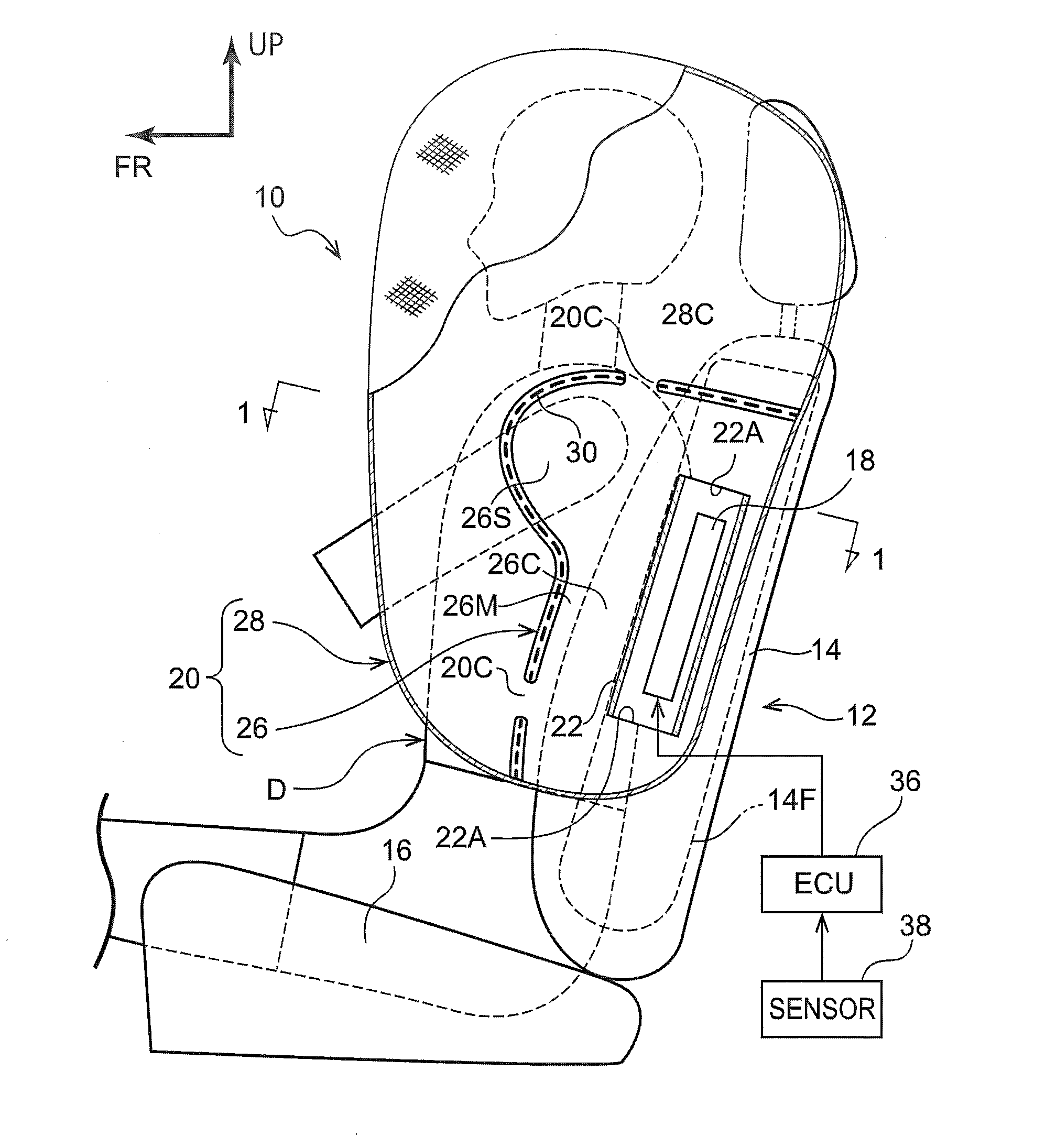
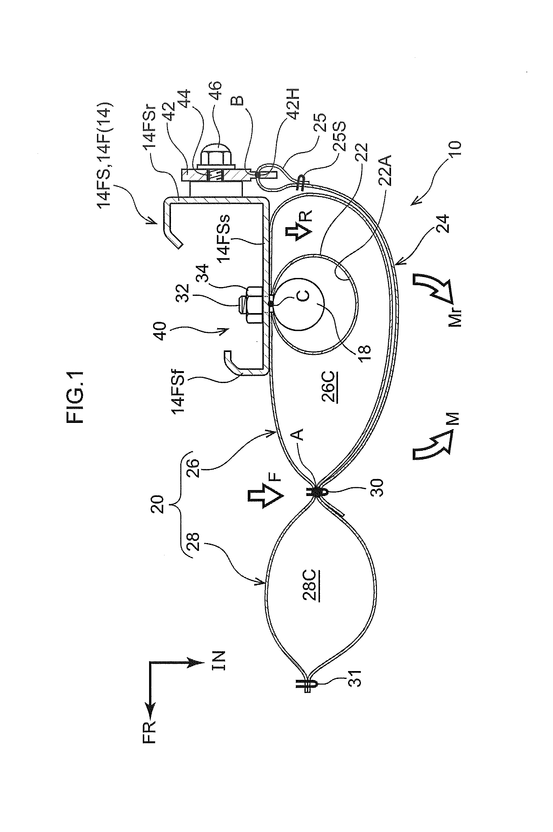
[0051]Explanation follows regarding a far side airbag device 10 according to a first exemplary embodiment of the present invention, with reference to FIG. 1 to FIG. 3. Note that in the drawings, the arrow FR, the arrow UP, and the arrow IN respectively indicate the vehicle front direction, the vehicle upward direction, and the vehicle center side in the vehicle width direction, as appropriate. In the following explanation, unless specifically indicated, reference simply to the front and rear, up and down, and left and right directions refers to the front and rear in the vehicle front-rear direction, up and down in the vehicle up-down direction, and left and right when facing toward the front in the vehicle front-rear direction.

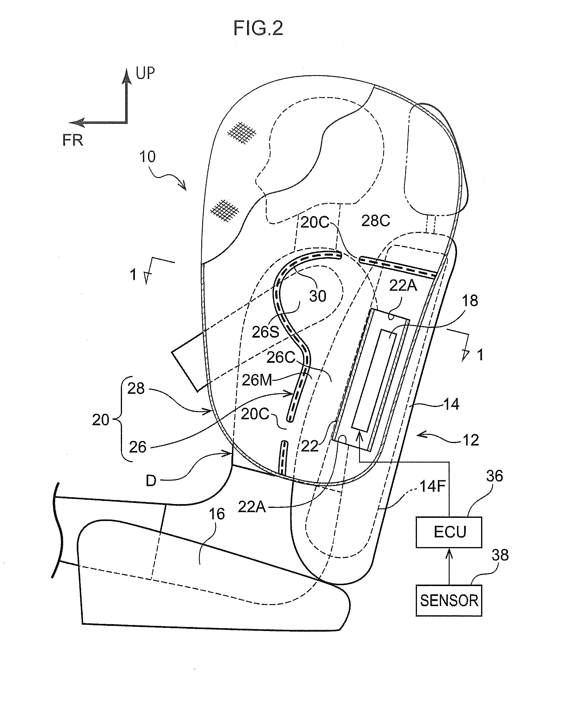
[0052]Schematic Overall Configuration of Far Side Airbag Device

[0053]As illustrated in FIG. 2, the far side airbag device 10 is installed to a seatback 14 of a vehicle seat 12. Specifically, the vehicle seat 12 is disposed offset to either the left or right si...

second exemplary embodiment

[0098]FIG. 4 is a cross-section corresponding to FIG. 1, illustrating a far side airbag device 50 according to a second exemplary embodiment of the present invention. The far side airbag device 50 differs from the far side airbag device 10 of the first exemplary embodiment in that it is additionally provided with a tension cloth 52, serving as an inside tension cloth, as well as the tension cloth 24, serving as an outside tension cloth.

[0099]One end of the inside tension cloth 52 is connected to the side airbag 20 at a portion positioned further toward the front than the seatback frame 14F when in an inflated and deployed state, and the other end is connected to the seatback frame 14F. In other words, a front end side of the inside tension cloth 52 is connected to the side airbag 20, and a rear end side of the tension cloth 52 is connected the seatback frame 14F. The tension cloth 52 is configured so as to receive tension accompanying inflation and deployment of the side airbag 20, ...

third exemplary embodiment

[0106]FIG. 5 is a cross-section corresponding to FIG. 1, illustrating a far side airbag device 60 according to a third exemplary embodiment of the present invention. The far side airbag device 60 differs from the far side airbag device 10 according to the first exemplary embodiment in that it is provided with a tension cloth 62, serving as an inside tension cloth, in place of the tension cloth 24, serving as an outside tension cloth.

[0107]One end of the inside tension cloth 62 is connected to the side airbag 20 at a portion positioned further toward the front than the seatback frame 14F in an inflated and deployed state, and the other end of the inside tension cloth 62 is connected to the seatback frame 14F. In other words, a front end side of the tension cloth 62 is connected to the side airbag 20, and a rear end side is connected to the seatback frame 14F. The tension cloth 62 is configured so as to receive tension accompanying inflation and deployment of the side airbag 20, and t...


PUM


Abstract

A far side airbag device comprising: a side airbag provided at a side section on a vehicle center side of a seatback, the side airbag comprising a rear inflation section and a front inflation section that inflates and deploys when supplied with gas through a communication path formed at a boundary with the rear inflation section; a fixing structure that fixes the side airbag to a seatback frame at the rear inflation section; and a tension cloth that receives tension and deploys accompanying inflation and deployment of the side airbag, wherein a vehicle front-rear direction front end side of the tension cloth is connected to the side airbag and a rear end side of the tension cloth is connected to the seatback frame, and in a deployed state, the tension cloth covers at least a portion of the rear inflation section as viewed from a side of the seatback.

Description

CROSS-REFERENCE TO RELATED APPLICATION[0001]This application claims priority under 35 USC 119 from Japanese Patent Application, No. 2014-128634 filed Jun. 23, 2014, the disclosure of which is incorporated by reference herein.BACKGROUND OF THE INVENTION[0002]1. Technical Field[0003]The present invention relates to a far side airbag device.[0004]2. Related Art[0005]Airbag devices, such as that described in Japanese Patent Application Laid-Open (JP-A) No. 2012-051557, are known in which a slit is formed in a non-inflating section disposed at a central portion of an airbag body, with one end of a tether that passes through the slit connected to a front end of the airbag body when inflated and deployed, and the other end of the tether connected to a seat structural member.[0006]Raising the internal pressure of an airbag is a simple and effective way to improve the restraint performance of a seated occupant by the airbag. Note that the airbag device of the above configuration is provided ...

Claims


Application Information

Patent Timeline
Patent Type & Authority Applications(United States)
IPC IPC(8): B60R21/207B60R21/231B60R21/216B60N2/90
CPCB60R21/207B60R2021/23146B60R21/23138B60R21/216B60R2021/23161B60R2021/23386
Inventor FUJIWARA, YUSUKE
Owner TOYOTA JIDOSHA KK
Why Eureka
Try Eureka