Optical readout device to provide visual information
a visual information and optical readout technology, applied in the direction of measuring circumference, mechanical diameter measurement, instruments, etc., can solve the problems of reading or interpreting the hash mark, measurement errors, order of magnitude,
- Summary
- Abstract
- Description
- Claims
- Application Information
AI Technical Summary
Benefits of technology
Problems solved by technology
Method used
Image
Examples
example 1
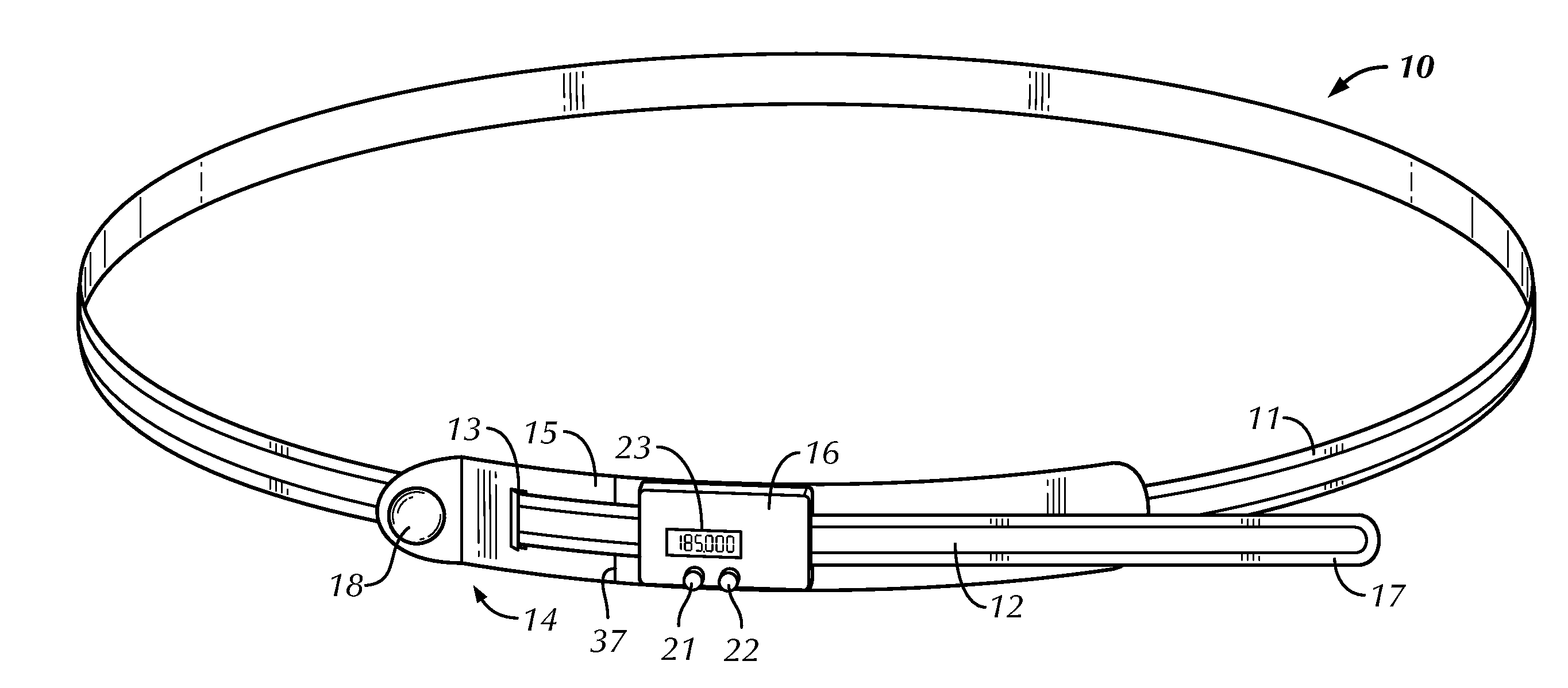
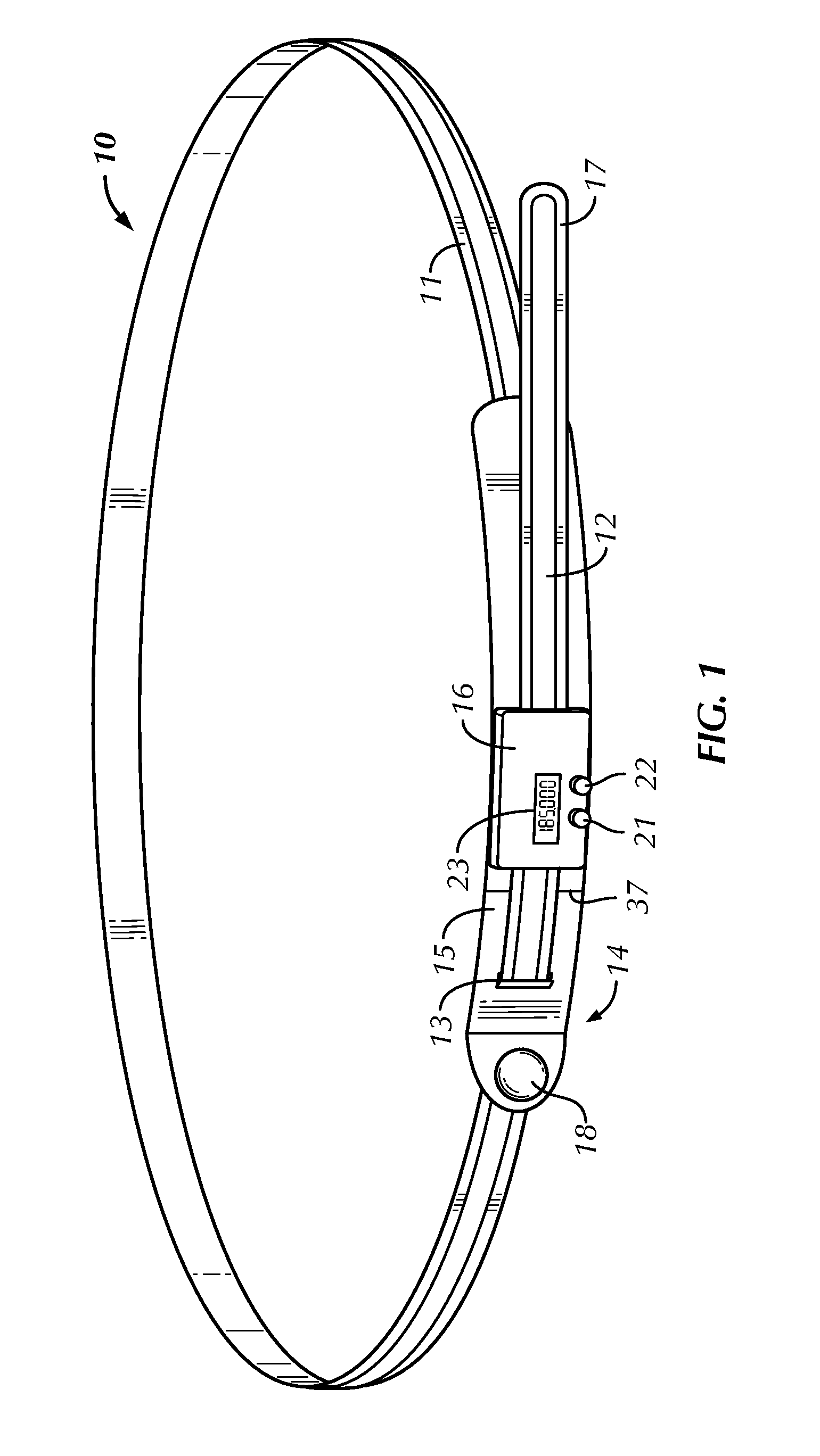
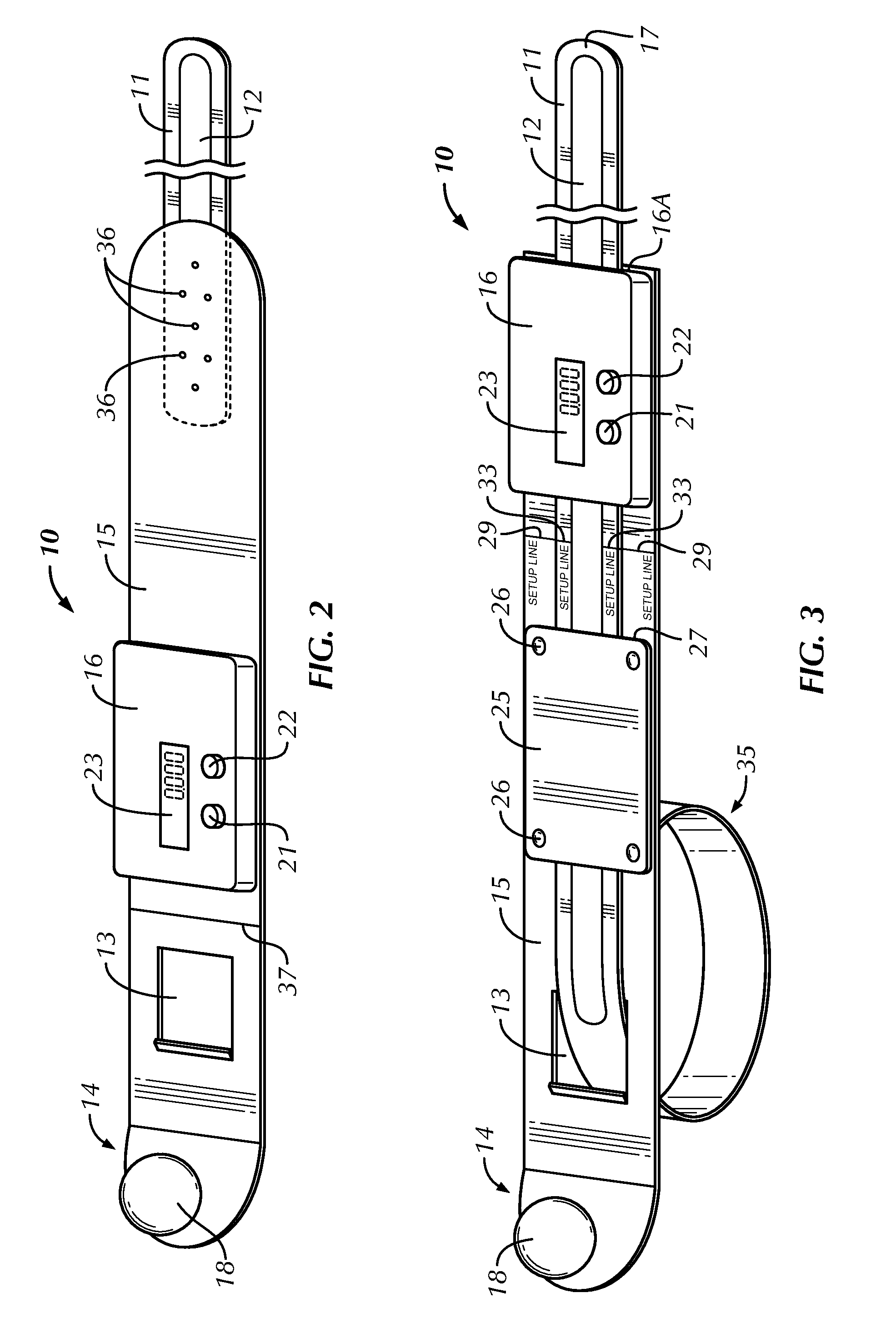
[0032]As shown in the FIG. 3 embodiment; tail end 17 of tape 11 is passed through opening 13, under guide plate 25 through gap 27, and through groove 16A in the back of digital device 16. For the small diameter embodiment shown in FIG. 3, tape 11 is pulled through until “setup line”33 on the machine readable outer side of the tape is aligned with setup line 29 on plate 15. For an instrument that is sized for a diameter range of 2 inches to 12 inches, the setup line alignment for the initial positioning process is at a three-inch diameter, which is the nominal size of tape loop 35 in FIG. 3.
[0033]When alignment is achieved, right button 22 is depressed and held to turn on. device 16 until a line of dashes is displayed in window 23. The tape is then pulled tight around the item to be measured, with about five pounds of tension, in window 23 initially appears one of the readings previously identified. Depressing left button 21 serially changes the readings between inches and metric, ci...
example 2
[0035]The apparatus shown in FIG. 2 operates in the same manner, hut it is structured for measuring larger diameter items, which can be of any practical diameter where precision is desired. In this embodiment, plate 15, if used at all, is much Larger and tape 11 can be affixed to it by rivets 36 as shown. Set up line 37 on plate 15 is shown, but the location of the setup line on the tape is not shown in this figure. However, the FIG. 2 embodiment is set up and used in the same way as the FIG. 3 embodiment. Differences relate primarily to the length of the plate, the length of the tape, and the location of the connection of the tape to the plate.
[0036]Digital device 16 may be battery powered, or could be externally powered. It may have wireless capability, so that an operator can record the readings on a computer, for example. USB port 32 (FIG. 4) is shown for external connections. Alternatively, a computer or other type of device, such as a smart phone or other electronic device, ma...
PUM
 Abstract
Description
Claims
Application Information
 - R&D
- Intellectual Property
- Life Sciences
- Materials
- Tech Scout
- Unparalleled Data Quality
- Higher Quality Content
- 60% Fewer Hallucinations
Browse by: Latest US Patents, China's latest patents, Technical Efficacy Thesaurus, Application Domain, Technology Topic, Popular Technical Reports.
© 2025 PatSnap. All rights reserved.Legal|Privacy policy|Modern Slavery Act Transparency Statement|Sitemap|About US| Contact US: help@patsnap.com


