Radar device, vehicle, and moving object speed detection method
- Summary
- Abstract
- Description
- Claims
- Application Information
AI Technical Summary
Benefits of technology
Problems solved by technology
Method used
Image
Examples
first embodiment
Modification of First Embodiment
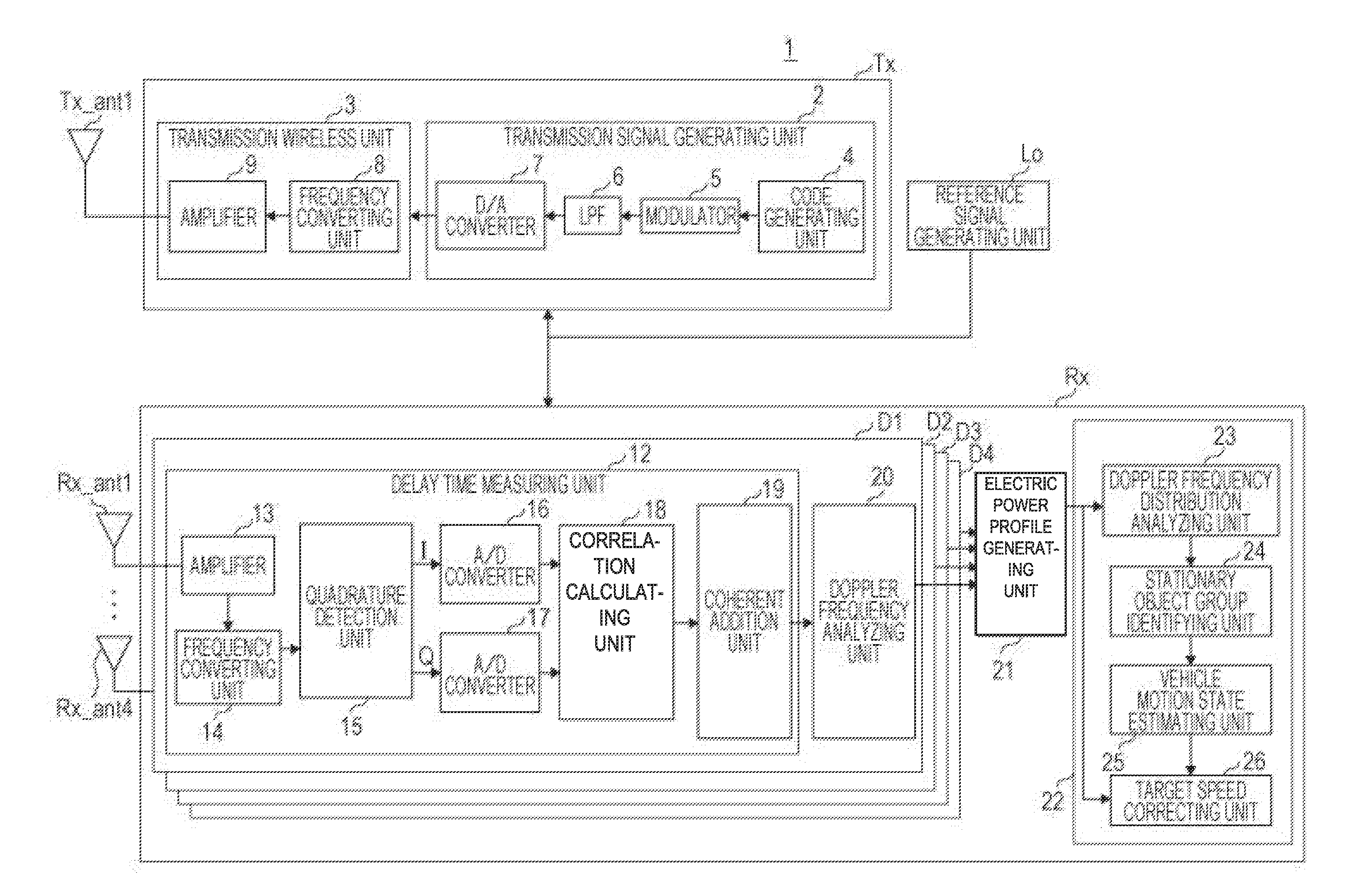
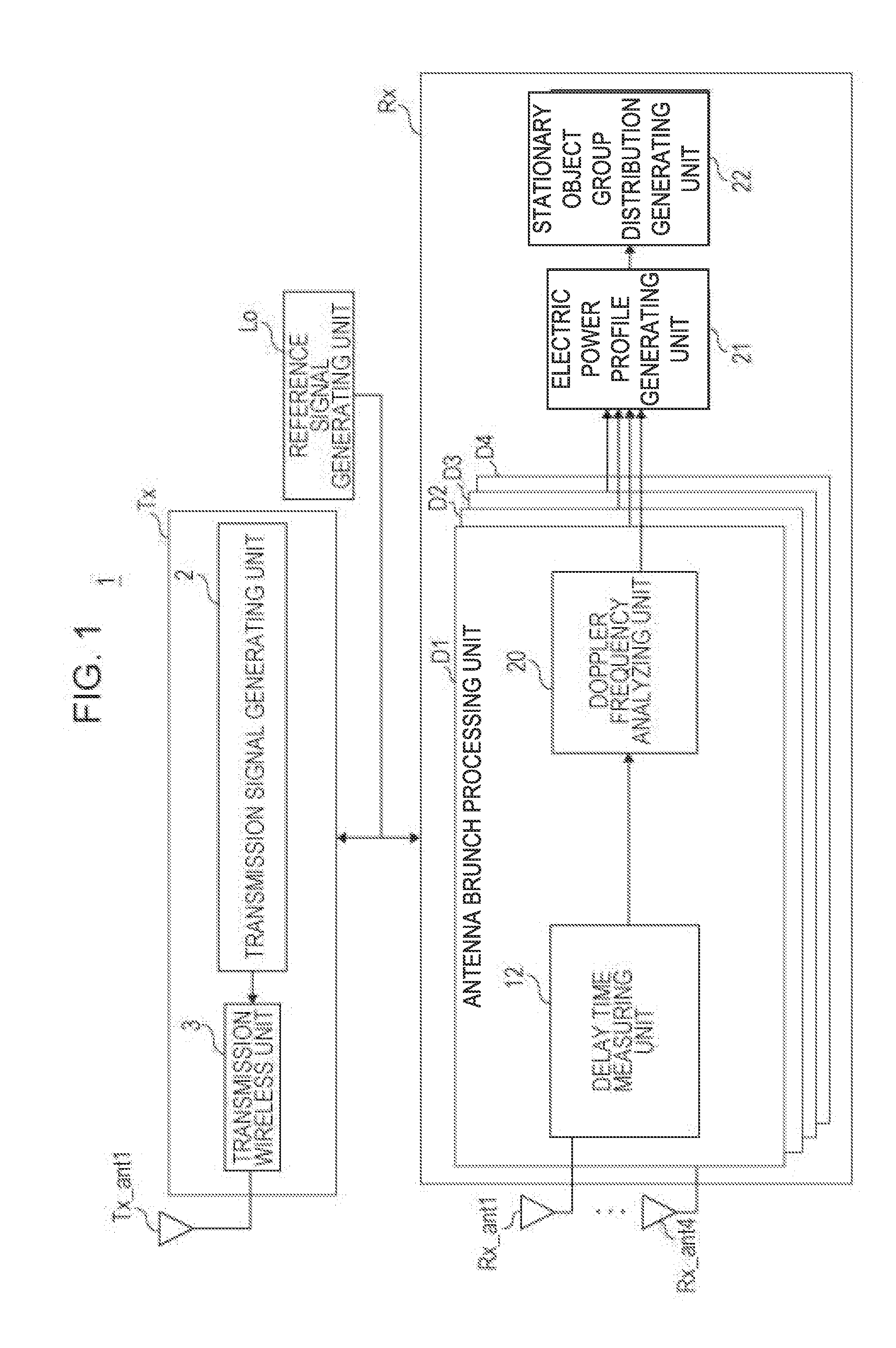
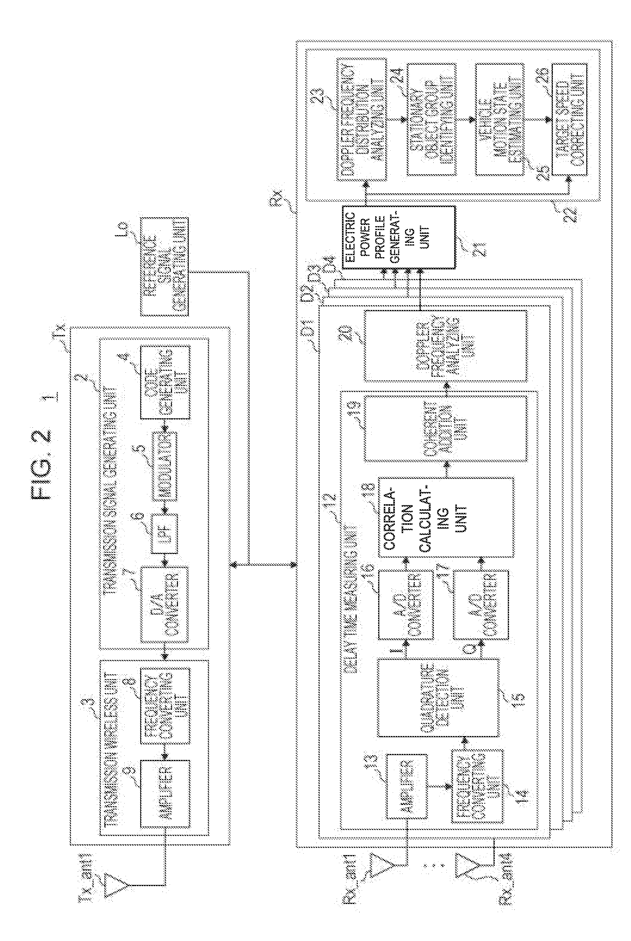
[0152]The configuration of a radar device according to a modification of the first embodiment (hereinafter referred to as “present modification”) is the same as the radar device 1 according to the first embodiment illustrated in FIG. 2, so description of the radar device 1 according to the present modification which would be redundant with the content of the radar device 1 according to the first embodiment will be simplified or omitted, and description will be made regarding content that is different.
[0153]The electric power profile Fout(k, fs, θu, w) obtained by the electric power profile generating unit 21 according to the first embodiment was three-dimensional data of discrete time k, Doppler frequency component fsΔθ, and azimuth angle θu. Accordingly, the amount of computation performed at the Doppler frequency distribution analyzing unit 23 and target speed correcting unit 26 using the electric power profile Fout(k, fs, θu, w) is great, and the m...
second embodiment
[0163]In a second embodiment, a vehicle motion state estimating unit 25A switches the vehicular speed of the vehicle CR between a vehicular speed detection value obtained from a vehicle sensor unit 31 installed in the vehicle CR and a vehicular speed estimated by the vehicle motion state estimating unit 25A (estimated value), in accordance with the detection state of the stationary object group.
[0164]FIG. 8 is a block diagram illustrating the internal configuration of a radar device 1A according to the second embodiment in detail. The configuration of the radar device 1A according to the present embodiment is a configuration where the radar device 1 according to the first embodiment illustrated in FIG. 2 further includes the vehicle sensor unit 31. Description of the radar device 1A according to the present embodiment which would be redundant with the content of the radar device 1 according to the first embodiment will be simplified or omitted, and description will be made regarding...
third embodiment
[0179]In a third embodiment, the configuration of a radar device 1B where the radar device 1A according to the second embodiment illustrated further includes a correction coefficient calculation storage unit 32, that calculates and stores correction coefficients for correcting the vehicular speed detection values obtained from the vehicle sensor unit 31, will be described with reference to FIG. 9.
[0180]FIG. 9 is a block diagram illustrating the internal configuration of the radar device 1B according to the third embodiment in detail. The configuration of the radar device 1B according to the present embodiment is a configuration where the radar device 1A according to the second embodiment illustrated in FIG. 8 further includes the correction coefficient calculation storage unit 32. Description of the radar device 1B according to the present embodiment which would be redundant with the content of the radar device 1A according to the second embodiment will be simplified or omitted, and...
PUM
 Abstract
Description
Claims
Application Information
 - R&D
- Intellectual Property
- Life Sciences
- Materials
- Tech Scout
- Unparalleled Data Quality
- Higher Quality Content
- 60% Fewer Hallucinations
Browse by: Latest US Patents, China's latest patents, Technical Efficacy Thesaurus, Application Domain, Technology Topic, Popular Technical Reports.
© 2025 PatSnap. All rights reserved.Legal|Privacy policy|Modern Slavery Act Transparency Statement|Sitemap|About US| Contact US: help@patsnap.com


