Stock level detector for roll machine for milling

Active Publication Date: 2016-03-10
SATAKE CORPORATION
View PDF7 Cites 13 Cited by
  • Summary
  • Abstract
  • Description
  • Claims
  • Application Information

AI Technical Summary

Benefits of technology

The present stock level detector has a load detector on the inlet part of a tube type supplying unit, with a detection rod that hangs in the unit. The load detector detects the level by applying a load to the rod in the vertical direction, improving detection precision. The detector can continuously and accurately detect the level of stock in the unit by measuring the change in the load on the rod. The detector is designed to easily receive the load of the stock flowing down in the unit. This design allows for accurate detection of the level of stock in the unit, even at high flow rates.

Problems solved by technology

However, since the sensor (108) described in Japanese Patent Laid-Open No. 2002-504854 has a configuration of providing the rod (110) and the load cell (108) protruding in the horizontal direction are connected in the L shape, the load received on the rod (110) is not applied to the load cell (108) in the vertical direction to generate twisting force at the connection part (X) of the rod (110) and the load cell (108), to cause harmful effect on the detection precision.

Method used


Image

  • Stock level detector for roll machine for milling
  • Stock level detector for roll machine for milling
  • Stock level detector for roll machine for milling

Examples


Embodiment Construction

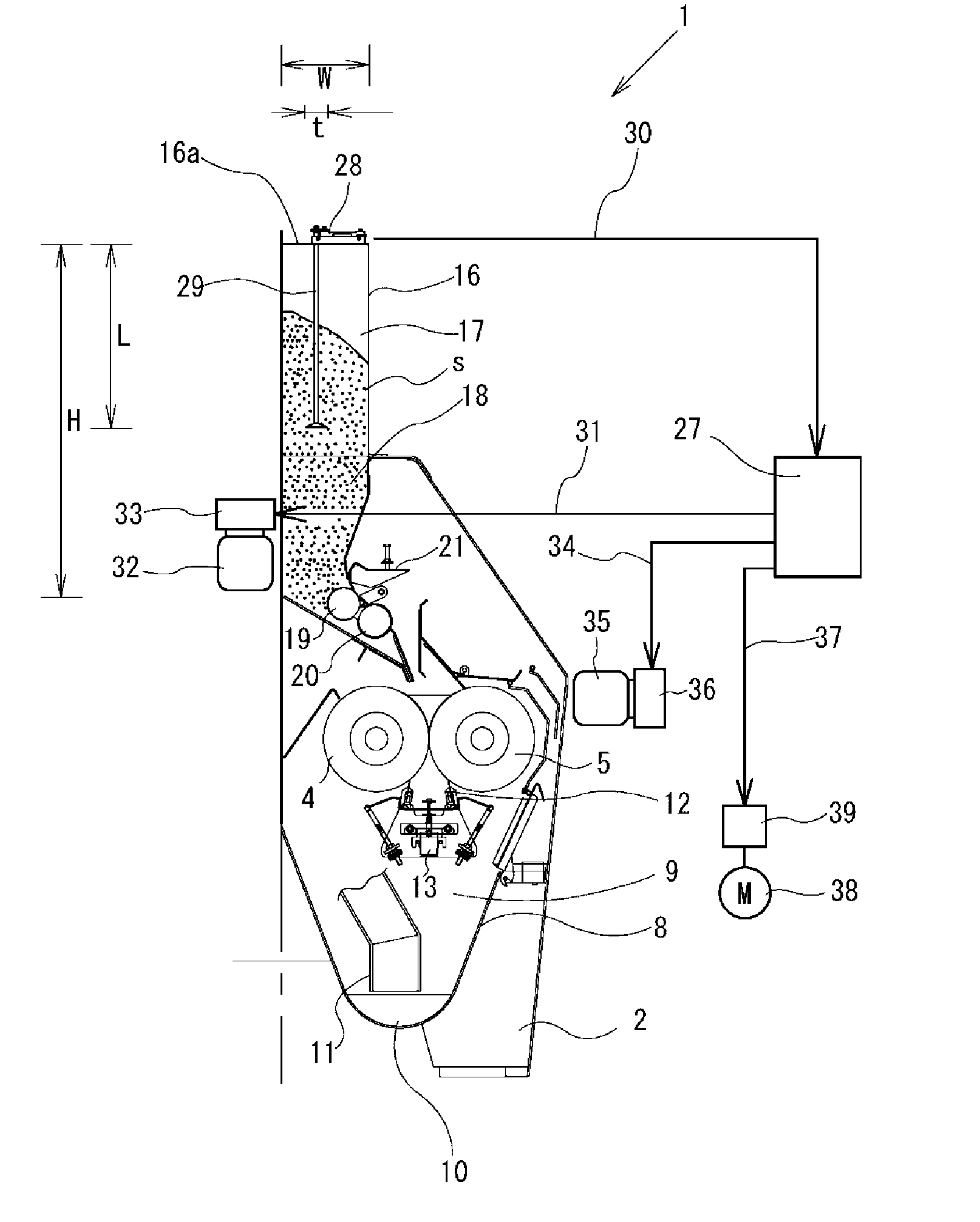
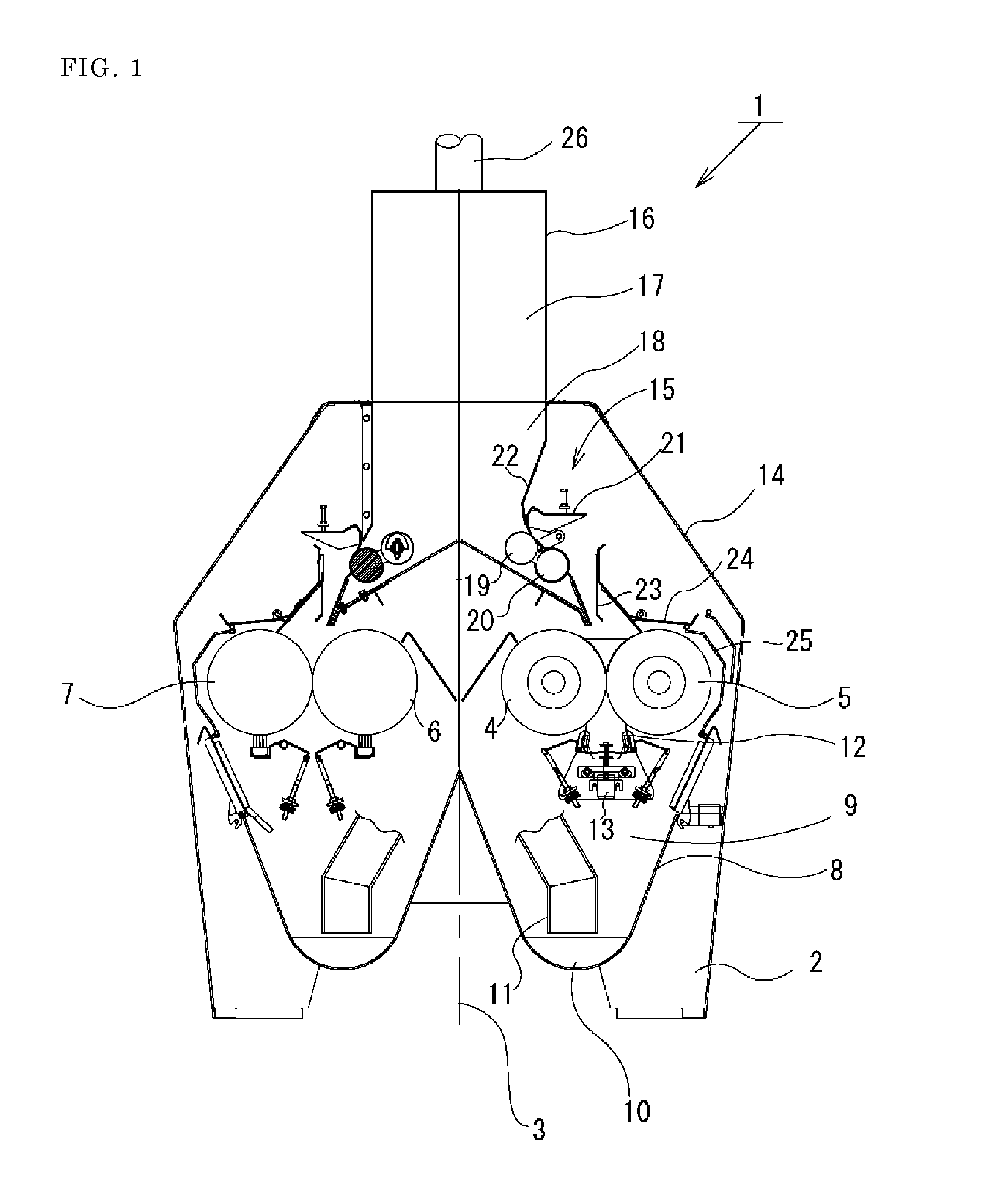
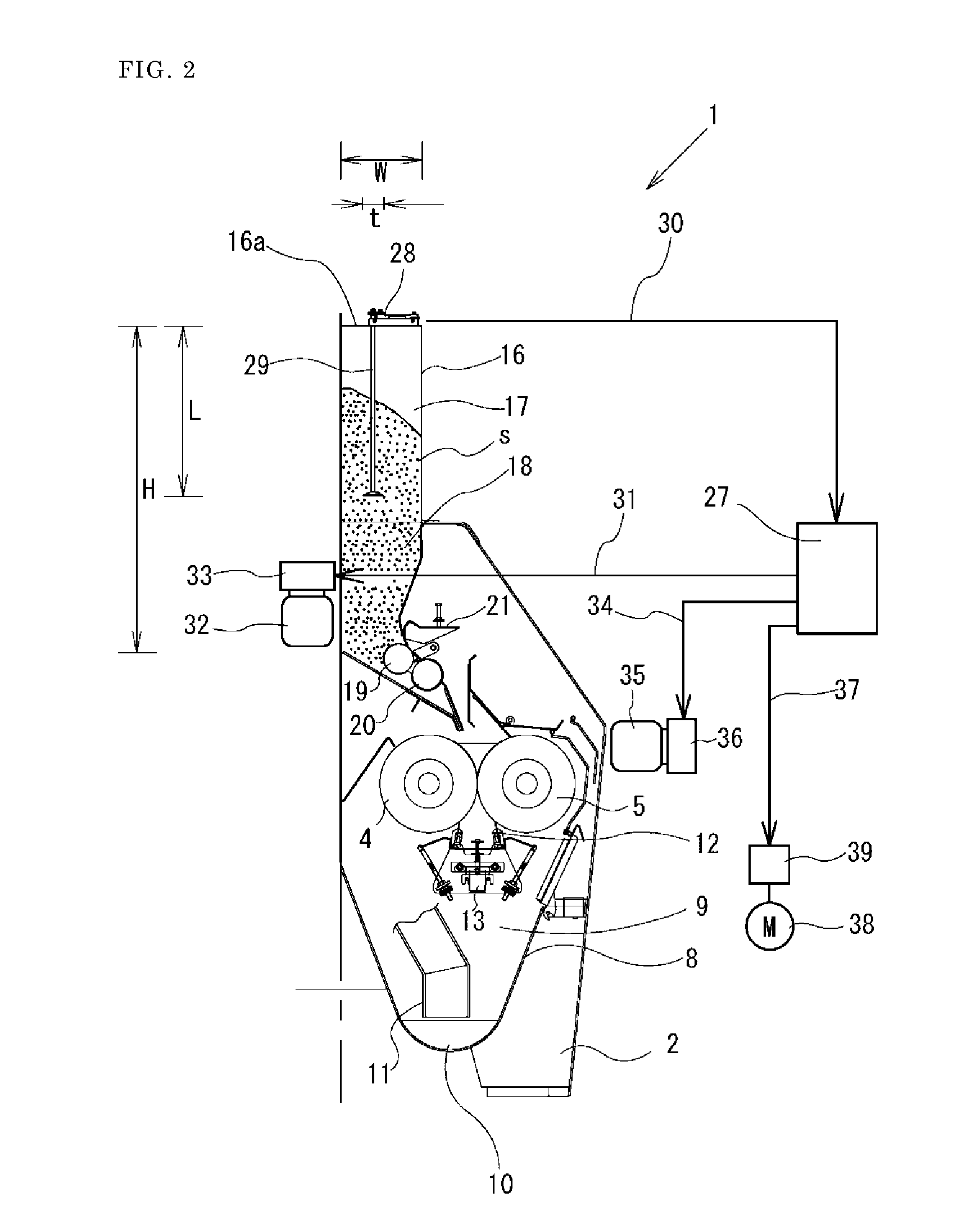
[0022]An embodiment of the present invention will be described with reference to the drawings. FIG. 1 is a schematic diagram illustrating entire configuration of a roll machine for milling according to the present invention. FIG. 2 is a schematic longitudinal section view illustrating configuration of a storing unit and a feeding unit according to the present invention. FIG. 3 is an oblique view illustrating attaching configuration of a rod and a load cell in a stock level detector according to the present invention.

[0023]As shown in FIG. 1, the roll machine for milling 1 has a partition plate 3 for dividing a frame 2 at the center, a pair of rolls 4, 5 and a pair of rolls 6, 7 symmetrical to each other. The pair of rolls 4, 5 and the rolls 6, 7 are integrally formed as a pack, and roll exchange can be immediately performed by attaching a bearing, a housing, a seal member, a spring, a roll gap adjustment device, and the like to the rolls 4, 5 (For example, Japanese Patent. Registrat...


PUM


Abstract

A roll machine for milling includes a tube type supplying unit 16, feed rolls 19, 20, a feeder gate plate 21, and main rolls 4, 5. A load detector 28 for detecting stock level is provided on inlet part 16a of the tube type supplying unit 16, a detection rod 29 for detecting the level is suspended in the tube type supplying unit 16, and one end of the detection rod 29 is connected to the load detector 28.

Description

BACKGROUND[0001]1. Technical Field[0002]The present invention relates to a stock level detector in a roll machine for milling.[0003]2. Background Art[0004]A stock level detector of a roll machine for milling disclosed in Japanese Patent Laid-Open No. 2002-504854 is known, which will be explained referring FIGS. 4 and 5. The sensor (108) for detecting the product of the roll machine for milling detects the weight (F) of the conveyed product. The sensor (108) is installed in the inlet part (102) for detecting the time when the sensor (108) is turned on and off, and for controlling the drive means (107). The sensor (108) includes the rod (110) for detecting the flow rate of the product by the weight. The rod (110) has a round cross section, and is supported in a direction vertical to the flowing direction of the product, that is, in the vertical direction, and supported on one while setting the other end as a free end. The sensor (108) detects the static constituent proportional to the...

Claims


Application Information

Patent Timeline
IPC IPC(8): B02C4/28B02C4/42G01F23/20
CPCB02C4/286G01F23/20B02C4/42B02C25/00
Inventor OKAMOTO, TAKESHIKAWANO, HIROYUKI
Owner SATAKE CORPORATION
Why Eureka
Try Eureka