Electric power converting apparatus

Active Publication Date: 2020-08-27
MITSUBISHI ELECTRIC CORP
View PDF0 Cites 1 Cited by
  • Summary
  • Abstract
  • Description
  • Claims
  • Application Information

AI Technical Summary

Benefits of technology

The present invention aims to solve the problem of measuring errors in an electric current sensor that includes a magnetoelectric transducer and a magnetic flux concentrating core. The technical effect of the invention is to provide an electric power converting apparatus that can suppress the measurement errors.

Problems solved by technology

Consequently, if a magnetoelectric transducer is disposed in a vicinity of the electric reactor, then the magnetoelectric transducer measures the magnetic leakage field leaking out from the electric reactor, and there is a risk that measurement errors in the electric current sensor may increase.

Method used


Image

  • Electric power converting apparatus
  • Electric power converting apparatus
  • Electric power converting apparatus

Examples


embodiment 1

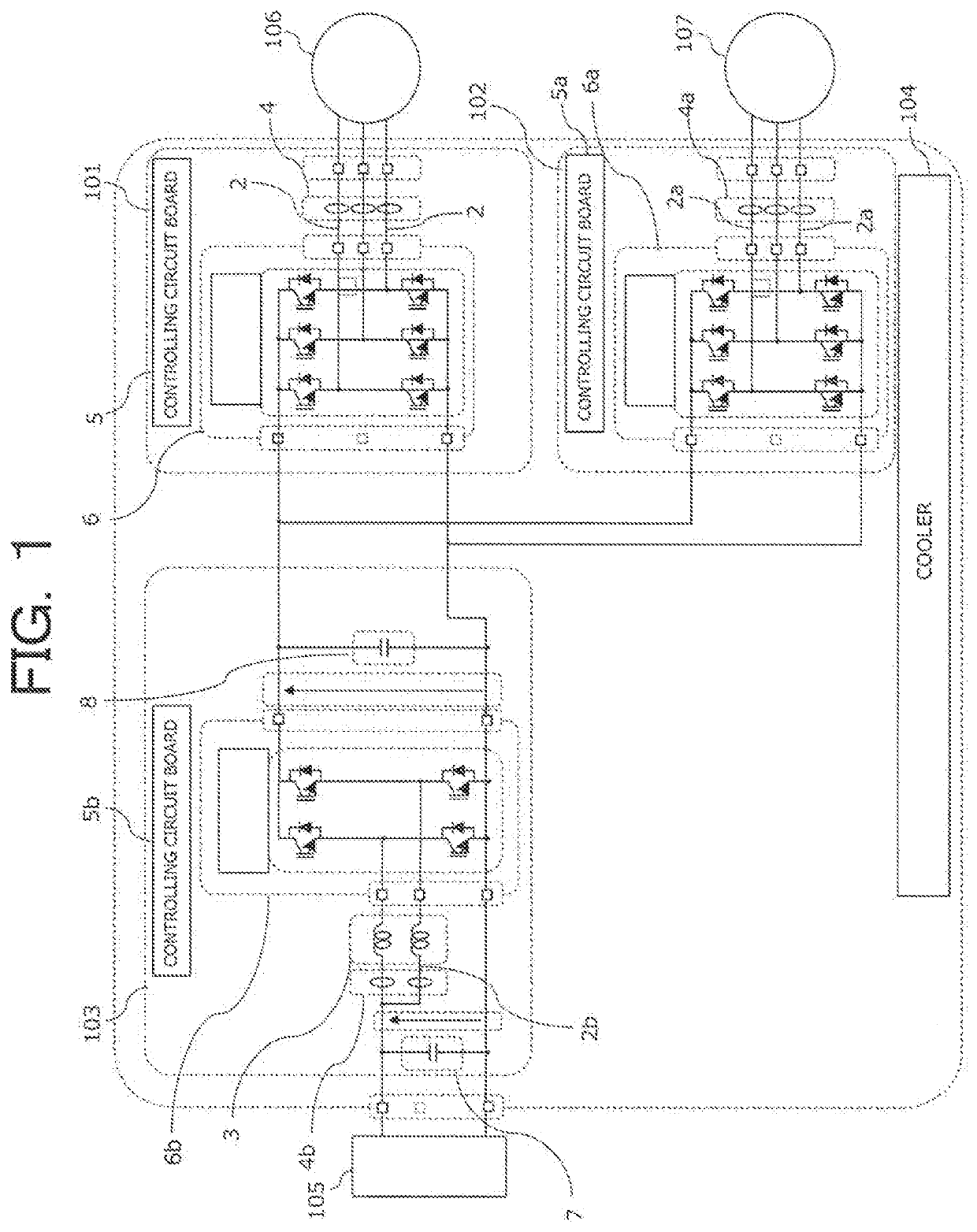
[0029]FIG. 1 is a circuit diagram for an electric power converting apparatus according to Embodiment 1 of the present invention. An electric power converting apparatus 1 is a device that converts electrical energy between an electric power supply and a load. In this example, an automotive electric power converting apparatus that is mounted to a vehicle such as a hybrid vehicle, or an electric vehicle, etc., is used as the electric power converting apparatus 1.

[0030]The electric power converting apparatus 1 is an electric power converting apparatus that includes a first inverter 101, a second inverter 102, a converter 103, and a cooler 104. The first inverter 101, the second inverter 102, and the converter 103 are cooled by the cooler 104.

[0031]The converter 103 is electrically connected to a battery 105. A high-voltage secondary battery is used as the battery 105. The first inverter 101 and the second inverter 102 are both electrically connected to the converter 103. The first inver...

embodiment 2

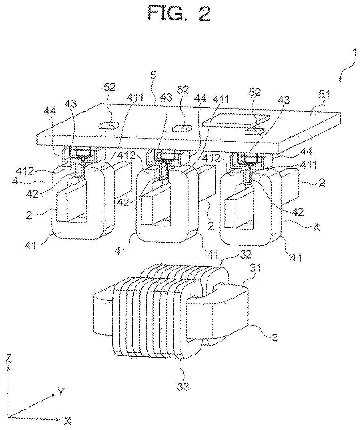
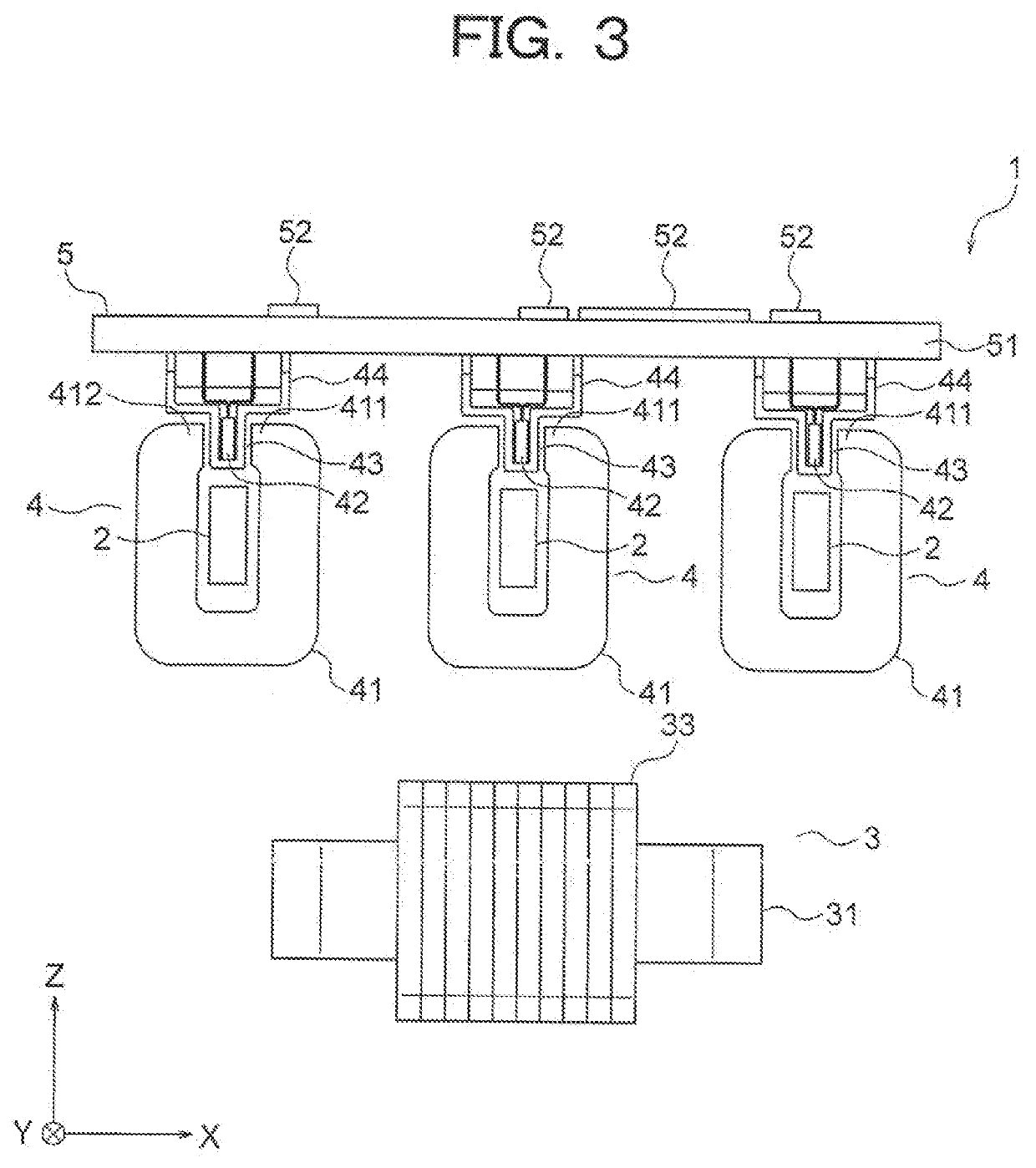
[0084]FIG. 12 is an oblique projection that shows an electric power converting apparatus according to Embodiment 2 of the present invention. FIG. 13 is a front elevation that shows the electric power converting apparatus from FIG. 12. The electric reactor 3 is disposed in a position that is separated from a plurality of electric current sensors 4 in a direction in which a plurality of busbars 2 line up, that is, in an X direction. At least a portion of the electric reactor 3 overlaps with limits of the plurality of electric current sensors 4 in a direction that is perpendicular to a plane that includes the plurality of busbars 2, that is, in a Z direction.

[0085]Configuration and orientation of the electric reactor 3 is similar or identical to those in Embodiment 1. Consequently, a direction A1 of the magnetic leakage field in the electric reactor 3 is a direction that is different than the core opening directions B1 of all of the magnetic flux concentrating cores 41. A remainder of ...

embodiment 3

[0087]FIG. 14 is an oblique projection that shows an electric power converting apparatus according to Embodiment 3 of the present invention. FIG. 15 is a front elevation that shows the electric power converting apparatus from FIG. 14. A plurality of notch portions 53 are formed on an edge portion of a circuit board 51 that is parallel to an X direction. A portion of the circuit board 51 is thereby disposed as a plurality of projecting portions 51a between the plurality of notch portions 53. The plurality of projecting portions 51a are disposed so as to be spaced apart from each other in the X direction so as to be aligned with positions of a plurality of busbars 2.

[0088]Magnetic flux concentrating cores 41 are disposed in a state in which first end portions 411 and second end portions 412 are inserted into the notch portions 53. The plurality of projecting portions 51a are thereby inserted individually into a measuring space 43 of each of the magnetic flux concentrating cores 41.

[00...


PUM


Abstract

In the electric power converting apparatus, an electric current sensor that measures an electric current that flows through a busbar includes: a magnetic flux concentrating core that has a first end portion and a second end portion that face each other so as to have a measuring space interposed; and a magnetoelectric transducer that has a magnetically sensitive portion that is disposed in the measuring space. The magnetoelectric transducer generates a signal in response to a magnitude of a magnetic field that is sensed by the magnetically sensitive portion. Where a core opening direction of the magnetic flux concentrating core is a direction that is directed from the busbar, through the measuring space, and outward from the magnetic flux concentrating core, a direction of the magnetic leakage field at the electric reactor is a direction that is different than the core opening direction.

Description

BACKGROUND OF THE INVENTION1. Field of the Invention[0001]The present invention relates to an electric power converting apparatus that includes an electric current sensor that measures electric current that flows through a busbar.2. Description of the Related Art[0002]Conventionally, electric power converting apparatuses are known in which electric current that flows through a busbar is measured by an electric current sensor in order to control output electric power to a motor. In conventional electric power converting apparatuses of this kind, a magnetoelectric transducer that outputs a signal in response to the magnitude of a magnetic field may be used as the electric current sensor. The electric current that flows through the busbar is measured by the magnetoelectric transducer outputting the signal in response to the magnitude of the magnetic field that arises around the busbar.[0003]At the same time, in conventional electric power converting apparatuses, an electric reactor can...

Claims


Application Information

Patent Timeline
IPC IPC(8): G01R15/20H02M7/00H02G5/02H01F27/24H05K1/18
CPCH02M7/003H01F27/24G01R15/207H02G5/02H02M3/158H05K2201/10151H05K1/181H02M7/53871H02M7/5387G01R19/0092H02M3/1584H02M1/14G01R31/42H01F3/14H01F37/00H05K3/301H05K2201/086H02M1/0009H02M1/007
Inventor NAKADA, MUNEKIUENO, SHUICHIISHII, SATOSHIYAMADA, TOMONORI
Owner MITSUBISHI ELECTRIC CORP
Why Eureka
Try Eureka