Image forming apparatus

a technology of image forming apparatus and forming apparatus, which is applied in the direction of electrographic process apparatus, printing, instruments, etc., can solve the problems of deteriorating correction accuracy and measurement error for time intervals, and achieve the effect of suppressing measurement errors and improving correction accuracy

Inactive Publication Date: 2015-07-28
CANON KK
View PDF10 Cites 6 Cited by
  • Summary
  • Abstract
  • Description
  • Claims
  • Application Information

AI Technical Summary

Benefits of technology

[0010]The present invention has been made in view of the above-mentioned problem. The present invention in one aspect provides a technique, in an optical scanning apparatus including multiple light emitting elements, of suppressing measurement errors when measuring an interval between light beams emitted from two light emitting elements, and improving correction accuracy for the image writing start positions of the light emitting elements.
[0012]According to the present invention, it is possible to provide a technique, in an optical scanning apparatus including multiple light emitting elements, of suppressing measurement errors when measuring an interval between light beams emitted from two light emitting elements, and improving correction accuracy for the image writing start positions of the light emitting elements.

Problems solved by technology

In such a case, there is a possibility that an error will occur in the measurement result for the time interval.
As a result, there is a possibility that an error will occur in the measurement result for the time interval between the detection signals output from the optical sensor, and the correction accuracy for the light beam emission timings will deteriorate.

Method used


Image

  • Image forming apparatus
  • Image forming apparatus
  • Image forming apparatus

Examples


embodiment 1

[0050

[0051]In Embodiment 1, the two light beams that are to be used for beam interval measurement (first and second beams) are selected in advance, and information indicating the two selected light beams is stored in advance in a memory (storage apparatus), at the time of factory shipping of the image forming apparatus 1 (or the optical scanning unit 2). When the beam interval measurement is executed, the two light emitting elements that are to emit the two light beams indicated by the information stored in the memory are selected (set) as the two light emitting elements to be used in the beam interval measurement, in accordance with that information.

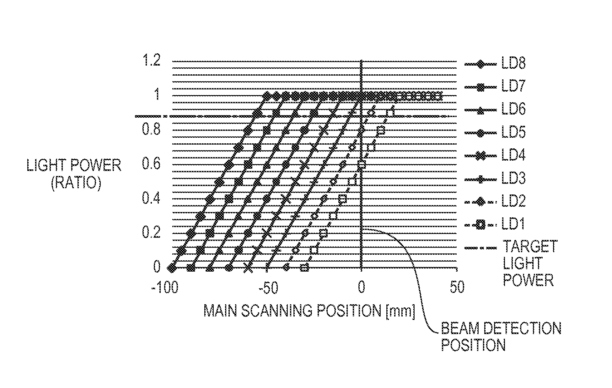
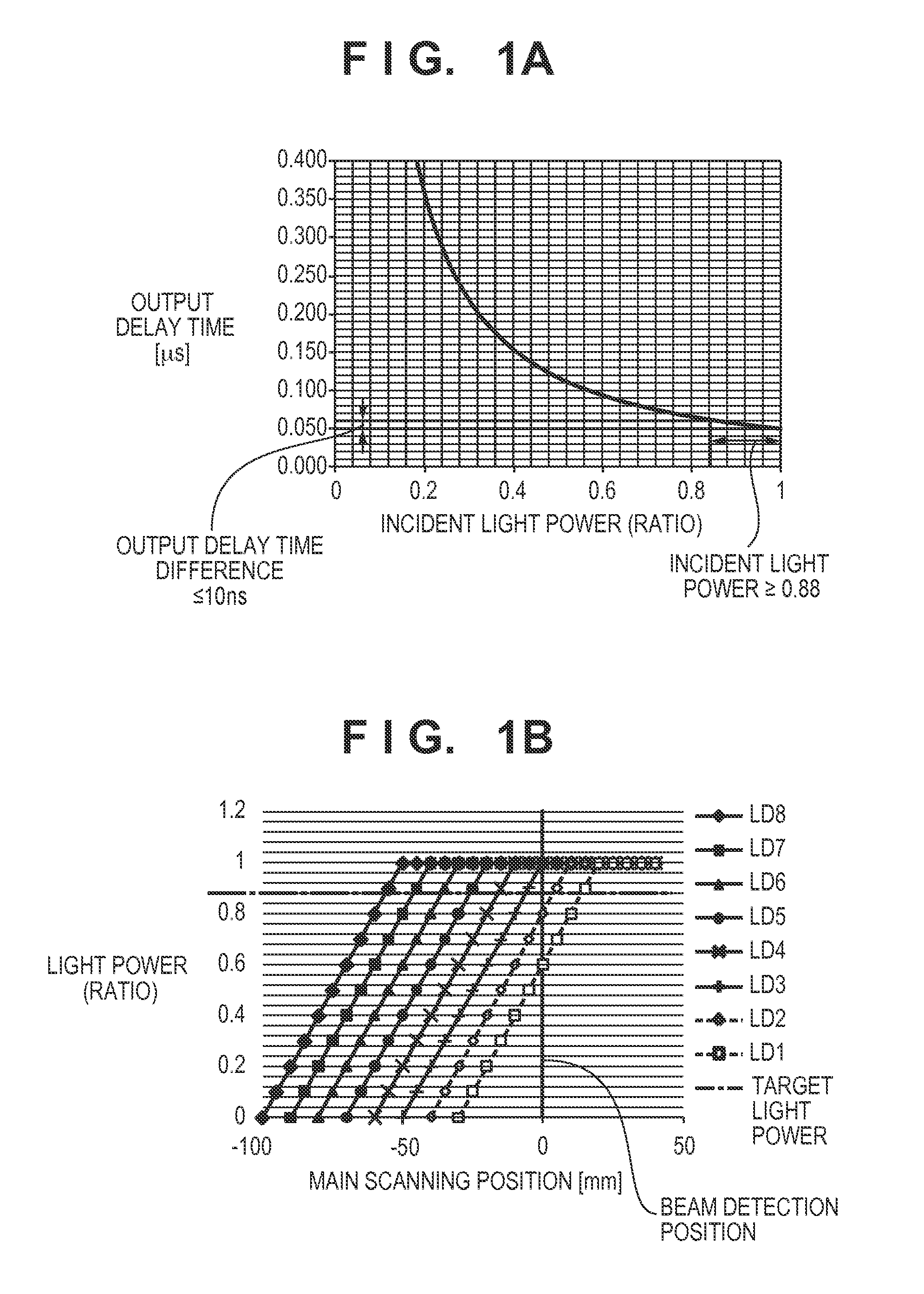
[0052]The method of selecting the light beams that are to be used in the beam interval measurement will be described first with reference to FIGS. 1A and 1B once again. FIG. 1A is a diagram showing a relationship between the delay time for a signal output from the optical sensor and the light power of the light beam that is incident on ...

embodiment 2

[0067

[0068]Embodiment 2 is a modified example of Embodiment 1 in which the light power of the light beams when performing the beam interval measurement, and the light power of the light beams when multiple light beams scan image regions on the photosensitive drums 25 in which electrostatic latent images are to be formed, are controlled so as to be different light powers. Note that portions that are different from Embodiment 1 will be described in particular below.

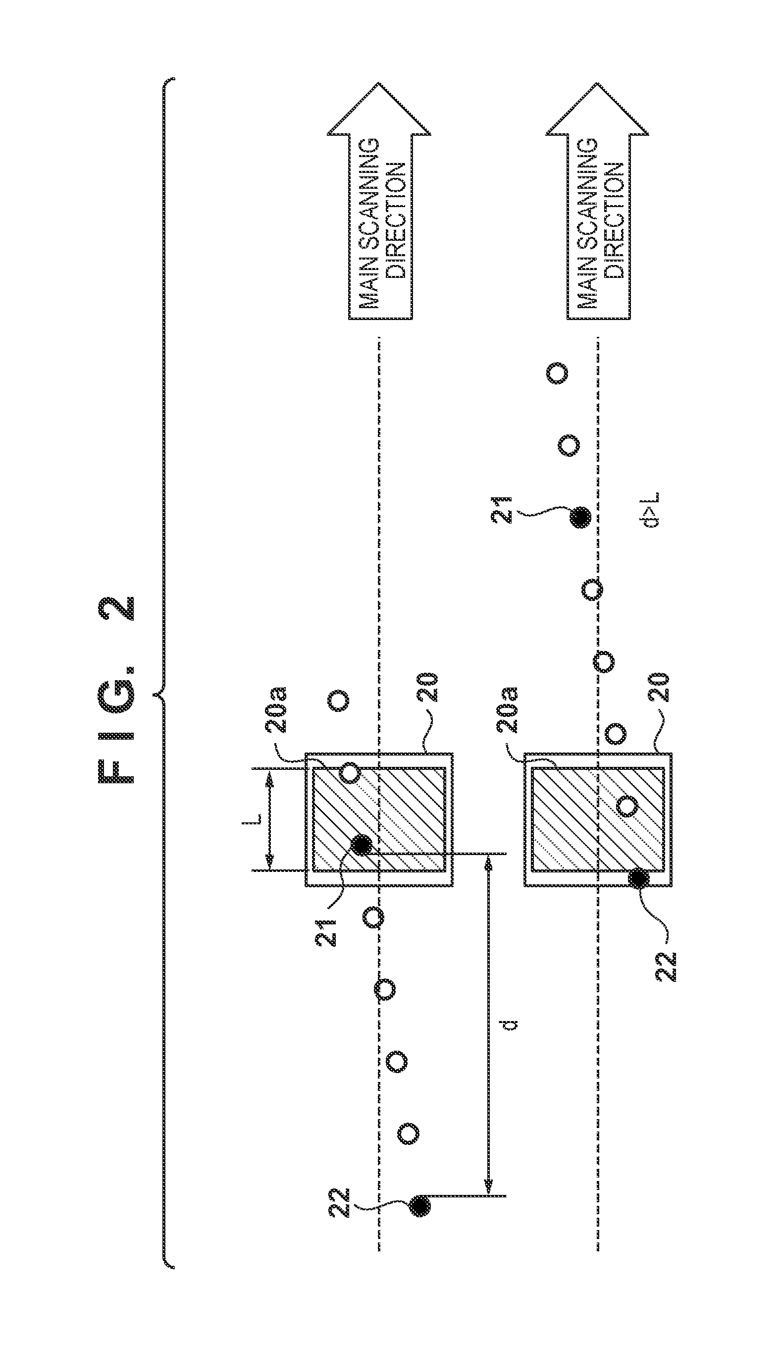
[0069]FIG. 6A is a block diagram showing the configuration of the scanner control unit 3 according to the present embodiment, and FIG. 6B is a timing chart showing the timing of operations performed by the scanner control unit 3. The present embodiment differs from Embodiment 1 (FIG. 3) in that a CPU 200 is newly provided outside of the scanner control unit 3, and a light power switching unit 45 is newly provided inside of the scanner control unit 3. Note that the scanner control unit 3, the magnification correction circuit...

embodiment 3

[0076

[0077]In Embodiment 3, the light power when the light beams that have been emitted from the light emitting elements (LD1 to LD8) of the semiconductor laser 11 are incident on the BD sensor 20 is measured, and the two light beams that are to be used in the beam interval measurement (first and second light beams) are selected based on the results of the measurement. Note that portions that are different from Embodiments 1 and 2 will be described in particular below.

[0078]FIG. 7A is a block diagram showing the configuration of the scanner control unit 3 according to the present embodiment. The present embodiment differs from Embodiment 2 (FIG. 6A) in that a light power measurement unit 80 is newly provided inside of the scanner control unit 3. Note that the scanner control unit 3, the magnification correction circuit 100, and the CPU 200 may be incorporated in the optical scanning unit 2, similarly to the cases of Embodiments 1 and 2.

[0079]In the present embodiment, the BD sensor ...


PUM


Abstract

An image forming apparatus controls a semiconductor laser such that first and second light beams among multiple light beams are successively incident on a BD sensor and measures the time interval between BD signals that correspond to the first and second light beams and are output from the BD sensor. Two light emitting elements that output two light beams for which the ratio between the light powers of two light beams detected by the detection unit falls within a predetermined range are set as light emitting elements that are to emit the first and second light beams when the time interval is to be measured. This suppresses measurement errors when measuring the interval between light beams emitted from two light emitting elements and improves correction accuracy for the image writing start positions of the light emitting elements.

Description

BACKGROUND OF THE INVENTION[0001]1. Field of the Invention[0002]The present invention relates to an electrophotographic image forming apparatus.[0003]2. Description of the Related Art[0004]Conventionally, there are known to be optical scanning apparatuses included in image forming apparatuses which employ a method of using a polygon mirror to deflect a group of light beams emitted from a semiconductor laser that includes multiple light emitting elements (light emitting units) and irradiate a photosensitive member (photosensitive drum) with the deflected light beams. With this kind of optical scanning apparatus, there are cases where the light beams emitted from the light emitting elements form images at positions on the photosensitive member that are different in the main scanning direction. In such a case, the writing start positions in the main scanning direction of the electrostatic latent images that are to be formed by the light beams emitted from the light emitting elements ne...

Claims


Application Information

Patent Timeline
Patent Type & Authority Patents(United States)
IPC IPC(8): B41J15/04G03G15/04G03G15/043
CPCG03G15/04072G03G15/0435G03G2215/0141
Inventor SEKI, YUICHI
Owner CANON KK
Why Eureka
Try Eureka