Electronic apparatus

Active Publication Date: 2015-12-24
PANASONIC INTELLECTUAL PROPERTY MANAGEMENT CO LTD
View PDF12 Cites 5 Cited by
  • Summary
  • Abstract
  • Description
  • Claims
  • Application Information

AI Technical Summary

Benefits of technology

[0030]According to the invention, when a two-dimensional coordinate obtained by attachment of water or the like being caused to be effective is prevented by using a strain sensor, even if a sampling interval for obtaining a two-dimensional coordinate from a touch panel is lon

Problems solved by technology

However, when a two-dimensional coordinate obtained by attachment of water or the like being caused to be effective is prevented by using a strain sensor, if an interval (sampling interval) for obtaining a two-dimensional coordinate from the touch panel is longer than a variation time of a strain quantity detected by the strain sensor, it may be difficult to accurately obtain variation in the strain quantity. FIG. 22 is a diagram illustrating an example when a sampling interval Ta for a two-dimensional coordinate

Method used


Image

  • Electronic apparatus
  • Electronic apparatus
  • Electronic apparatus

Examples


exemplary embodiment 1

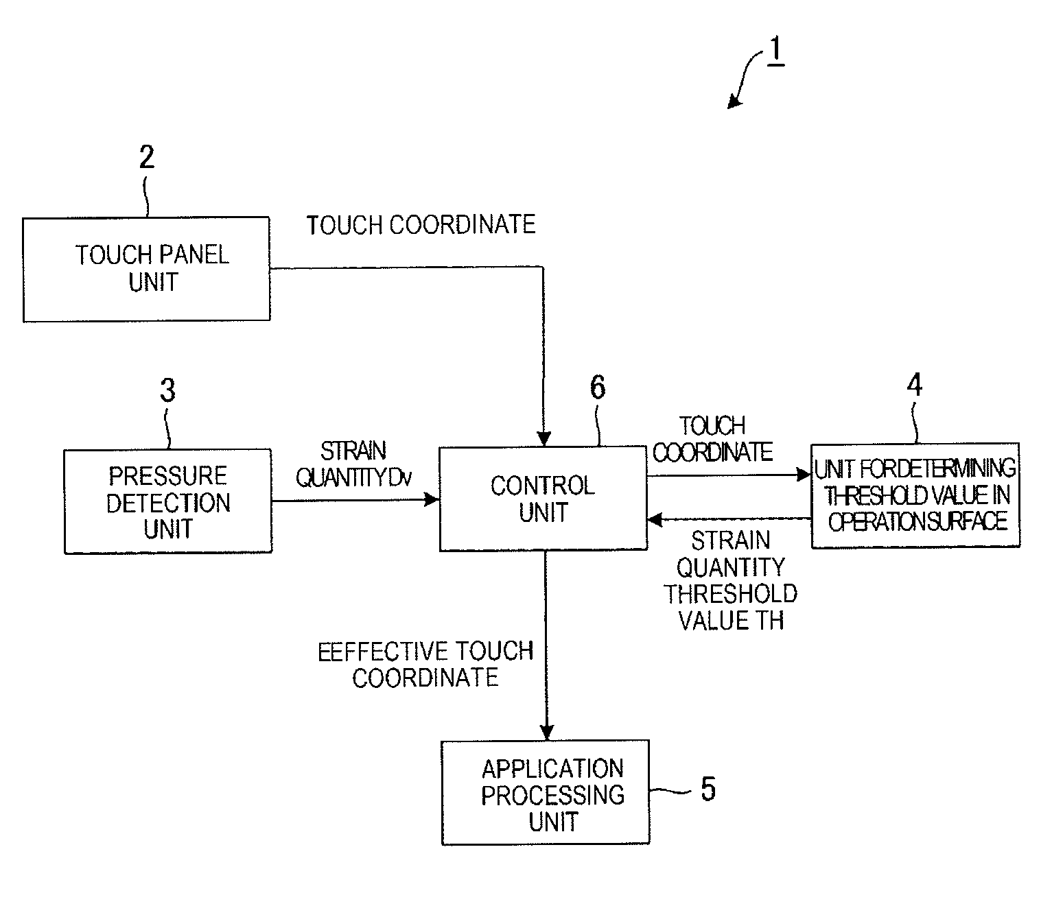
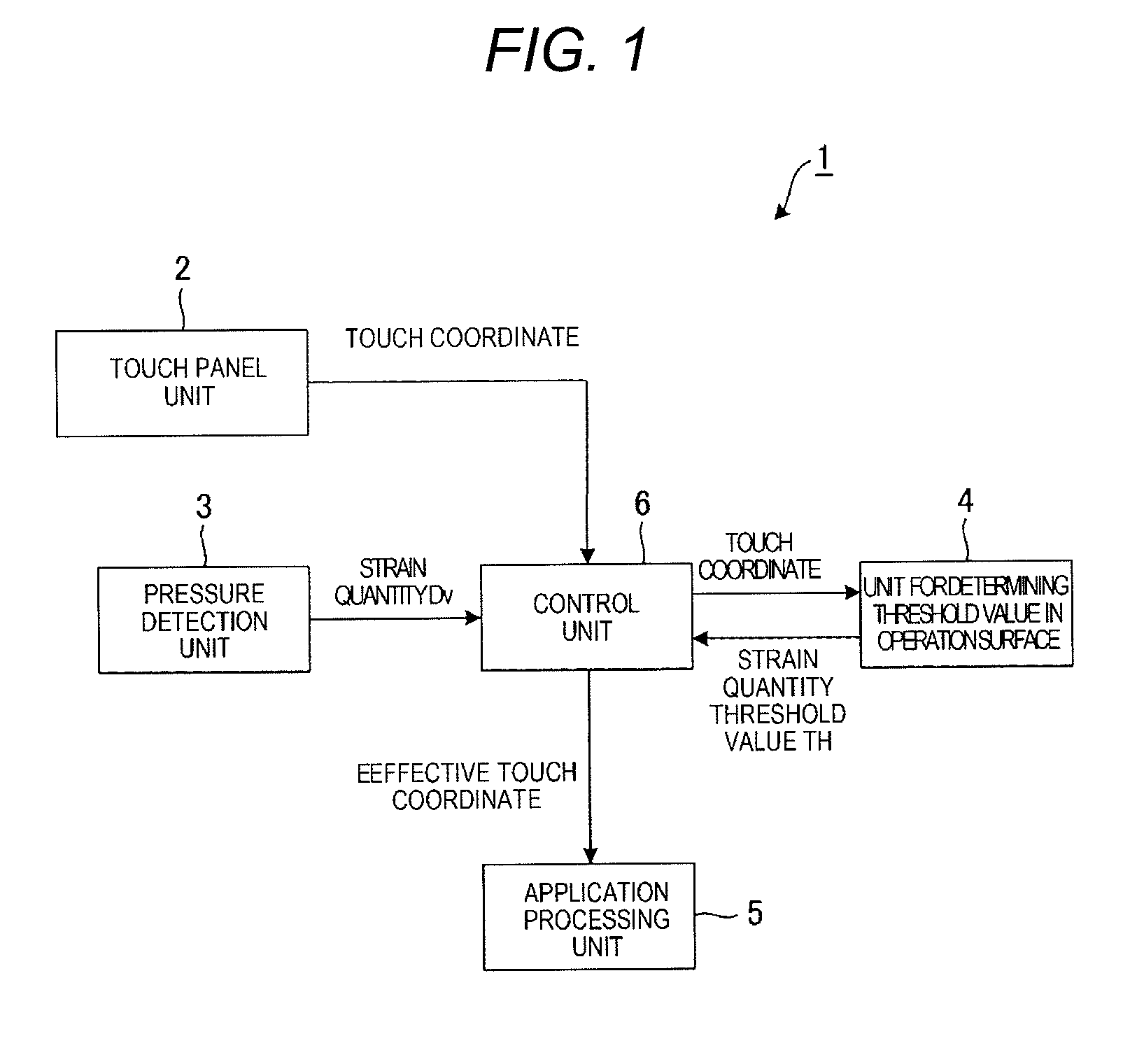
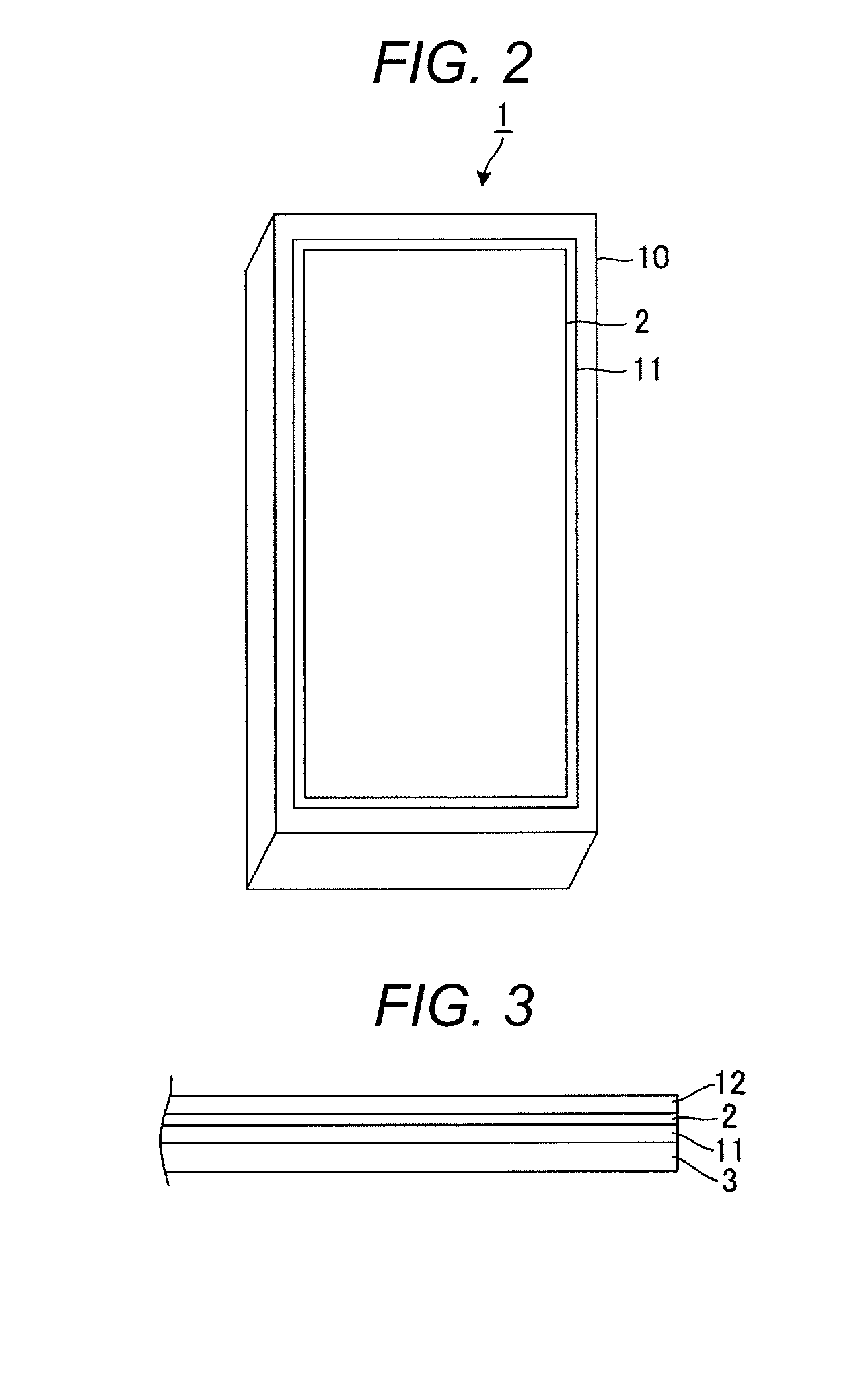
[0054]FIG. 1 is a block diagram illustrating a schematic configuration of an electronic apparatus according to Exemplary Embodiment 1 of the present invention. FIG. 2 is a perspective view illustrating the appearance of the electronic apparatus in FIG. 1. FIG. 3 is a cross-sectional view illustrating a pressure detection unit, a display unit, a touch panel unit, and a transparent member of the electronic apparatus in FIG. 1. The electronic apparatus 1 according to this exemplary embodiment is applied to a portable wireless device referred to as a smartphone, for example and a part functioning as a wireless device is not illustrated in the block diagram of FIG. 1.

[0055]In FIG. 1, the electronic apparatus 1 according to this exemplary embodiment includes the touch panel unit 2, the pressure detection unit 3, a unit for determining threshold value in operation surface 4, an application processing unit 5, and a control unit 6. As illustrated in FIG. 2, the electronic apparatus 1 accordi...

exemplary embodiment 2

[0072]FIG. 8 is a block diagram illustrating a schematic configuration of an electronic apparatus according to Exemplary Embodiment 2 of the present invention. In FIG. 8, components common as the above described components in FIG. 1 are denoted by the same reference numerals and descriptions thereof will be omitted. In the electronic apparatus 50 according to Exemplary Embodiment 2, variation in strain quantity may be also accurately obtained when a variation time of a strain quantity is shorter than an obtaining interval (sampling interval) of a touch coordinate and a strain quantity obtaining unit 51 is included as a unit for causing this to be possible.

[0073]FIG. 9 is a diagram illustrating a strain quantity obtaining process for determination in the electronic apparatus 50 according to Exemplary Embodiment 2. As illustrated in FIG. 9, a strain quantity obtaining unit 51 obtains a strain quantity Dv at an interval (below referred to as a “strain quantity obtaining interval Tb”) w...

exemplary embodiment 3

[0084]An electronic apparatus 60 according to Exemplary Embodiment 3 of the present invention includes a unit that can prevent determination of a touch coordinate obtained by a touch which is not an operation to be effective by mistake, and the touch is one of multi-touch detected by the touch panel unit 2. An example of a case where the touch panel unit 2 detects simultaneously a plurality of touch coordinates includes a case where one touch coordinate is obtained through an operation of a finger and the remaining touch coordinates are obtained by water. As illustrated in FIG. 12A, when water 90 is in the vicinity of the end of the operation surface 40 and an operation is performed in the vicinity of the center of the operation surface 40 with a finger 91, the water 90 and the finger 91 are brought onto contact with the operation surface 40 and thus touch coordinates corresponding to the water 90 and the finger 91 are output from the touch panel unit 2.

[0085]Since the finger 91 is ...


PUM


Abstract

A strain quantity obtaining unit is provided that obtains a strain quantity at an interval faster than variation in the strain to be detected and stores the maximum value of the strain quantity. When a touch coordinate is obtained at a predetermined sampling interval, if the maximum value of the strain quantity when the touch coordinate is obtained does not exceed a strain quantity threshold value, the touch coordinate is not caused to be effective. However, if the maximum value of the strain quantity when the touch coordinate is obtained exceeds a strain quantity threshold value, the touch coordinate is caused to be effective. If a touch coordinate is caused to be effective once, the touch coordinate is caused to be effective continuously until an instructing object is separated from an operation surface of a touch panel unit at a predetermined distance or more in a perpendicular direction.

Description

CROSS REFERENCE TO RELATED APPLICATIONS[0001]This application claims priority to Japanese Patent Application No. 2014-127381 filed Jun. 20, 2014, the entire contents of which are incorporated by reference herein.BACKGROUND OF THE INVENTION[0002]1. Field of the Invention[0003]The present invention relates to an electronic apparatus including a touch panel.[0004]2. Description of the Related Art[0005]An electronic apparatus such as a smartphone and a tablet, in which a touch panel is mounted, has come into wide use. The electronic apparatus may include an electrostatic capacitive touch panel. The electrostatic capacitive touch panel can receive “touch operation” performed by directly bringing a finger of a bare hand into contact with a surface of the touch panel and “hover operation” performed by causing a finger to be positioned at a predetermined height from the surface of the touch panel, without bringing the finger of the bare hand onto contact with the surface of the touch panel....

Claims


Application Information

Patent Timeline
IPC IPC(8): G06F3/047G06F3/041G09G5/00G06F3/044
CPCG06F3/047G06F3/044G09G2300/0426G09G5/003G06F3/0414G06F2203/04105G06F2203/04108G06F3/04186G06F3/0418
Inventor YAMAGUCHI, TAKESHITAKANO, TOMOKI
Owner PANASONIC INTELLECTUAL PROPERTY MANAGEMENT CO LTD
Why Eureka
Try Eureka