Filtering apparatus for correcting variation of CR-product

a filtering apparatus and cr-product technology, applied in the direction of pulse manipulation, pulse technique, line-transmission details, etc., can solve the problems of inaccurate correction of cr-product variation and inability to correctly detect cr-product variation, so as to achieve accurate correction, accurate detection, and constant frequency characteristics of filtering apparatus

Inactive Publication Date: 2009-02-17
PANASONIC CORP
View PDF4 Cites 8 Cited by
  • Summary
  • Abstract
  • Description
  • Claims
  • Application Information

AI Technical Summary

Benefits of technology

[0021]The object of the present invention is to solve the foregoing problem and to provide a filtering apparatus which correctly detects a variation of CR-product and accurately corrects a variation of frequency characteristics of the filtering apparatus even in the case where a plurality of reference signals having different frequencies from each other are used, and a semiconductor apparatus having the same.
[0031]According to the filtering apparatus and the semiconductor apparatus having the same according to the present invention, there is an effect that, even in the case where a plurality of reference signals having different frequencies from each other are used, a variation of CR-product of the reference filter in response to each of the plurality of reference signals can be correctly detected, a variation of frequency characteristics of the main filter can be accurately corrected, and the frequency characteristics of the filtering apparatus can be always substantially constant.

Problems solved by technology

Therefore, there is a problem in that, when the frequency of the reference signal Sa changes, the variation of the CR-product cannot be correctly detected, and the variation of frequency characteristics of the filtering apparatus cannot be accurately corrected.

Method used


Image

  • Filtering apparatus for correcting variation of CR-product
  • Filtering apparatus for correcting variation of CR-product
  • Filtering apparatus for correcting variation of CR-product

Examples


first preferred embodiment

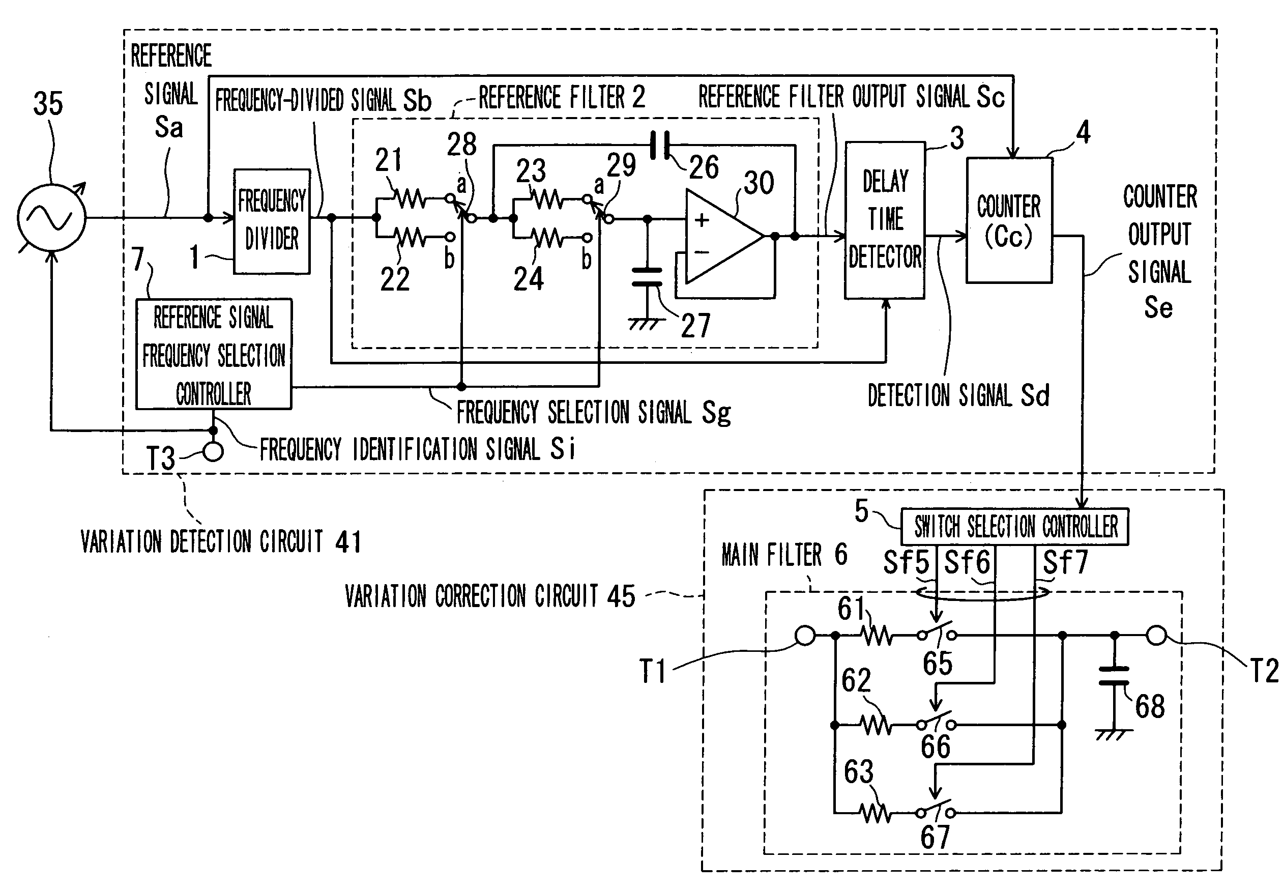
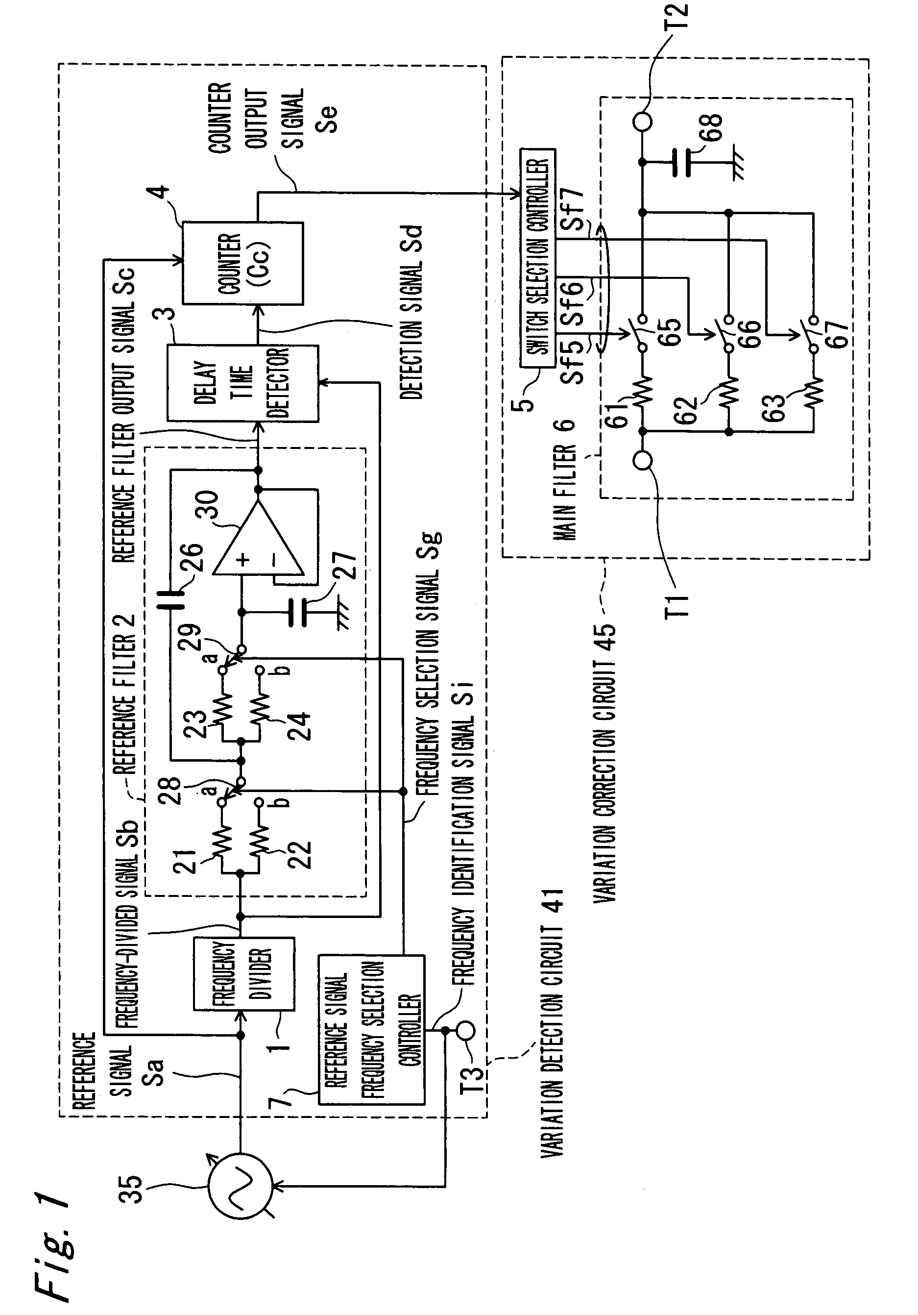
[0054]FIG. 1 is a block diagram showing a configuration of a filtering apparatus according to a first preferred embodiment of the present invention. Referring to FIG. 1, the filtering apparatus according to the present preferred embodiment is built in a semiconductor apparatus such as a semiconductor integrated circuit, and includes an oscillator 35, a variation detection circuit 41, and variation correction means 45. The variation detection circuit 41 includes a frequency divider 1, a reference filter 2, a delay time detector 3, a counter 4, and a reference signal frequency selection controller 7. The reference filter 2 includes resistors 21, 22, 23 and 24, capacitors 26 and 27, switches 28 and 29; and an amplifier 30. The variation correction circuit 45 includes a switch selection controller 5 and a main filter 6. The main filter 6 includes resistors 61, 62 and 63, switches 65, 66 and 67 connected in series to the resistors 61, 62 and 63, respectively, and a capacitor 68.

[0055]Ref...

second preferred embodiment

[0075]FIG. 4 is a block diagram showing a configuration of a filtering apparatus according to a second preferred embodiment of the present invention. The filtering apparatus of the present preferred embodiment is different in that a variation detection circuit 41A is provided in place of the variation detection circuit 41, as compared with the filtering apparatus according to the first preferred embodiment shown in FIG. 1. The variation detection circuit 41A is different in that a frequency division ratio change circuit 8 is further provided, and a reference filter 2A is provided in place of the reference filter 2, as compared with the variation detection circuit 41 of FIG. 1. The other configurations other than that are the same as the filtering apparatus according to the first preferred embodiment shown in FIG. 1, and repeated description of components labeled with the same reference numerals will be omitted.

[0076]Referring to FIG. 4, the frequency division ratio change circuit 8 ...

third preferred embodiment

[0082]FIG. 7 is a block diagram showing a configuration of a filtering apparatus according to a third preferred embodiment of the present invention. The filtering apparatus of the present preferred embodiment is different in that a variation detection circuit 41B is provided in place of the variation detection circuit 41, as compared with the filtering apparatus according to the first preferred embodiment shown in FIG. 1. The variation detection circuit 41B is different in that a reference filter 2A and a counter 4A are provided in place of the reference filter 2 and the counter 4, as compared with the variation detection circuit 41 of FIG. 1. The other configurations other than that are the same as the filtering apparatus according to the first preferred embodiment shown in FIG. 1, and repeated description of components labeled with the same reference numerals will be omitted.

[0083]Referring to FIG. 7, a reference signal frequency selection controller 7 outputs a frequency selectio...


PUM


Abstract

A filtering apparatus includes a main filter, a variation detection circuit, and a variation correction circuit. The variation detection circuit includes a reference filter having at least one resistor and at least one capacitor, detects a variation of CR-product based on the resistor and the capacitor of the reference filter in response to each of a plurality of reference signals having different frequencies from each other, and then outputs a variation detection signal indicating a detected result. The variation correction circuit corrects frequency characteristics of the main filter on the basis of the variation detection signal.

Description

BACKGROUND OF THE INVENTION[0001]1. Field of the Invention[0002]The present invention relates to a filtering apparatus and a semiconductor apparatus having the same, and in particular, relates to the filtering apparatus which detects and corrects a variation of CR-product, which is a product of a resistance value of a resistor and a capacitance value of a capacitor, that determines frequency characteristics of the filtering apparatus in response to each of a plurality of reference signals having different frequencies from each other, and the semiconductor apparatus having the same.[0003]2. Description of the Related Art[0004]In recent years, in a mobile communication apparatus and the like, a filtering apparatus has high tendency to be built into a semiconductor apparatus in order to meet the increasing demand of reduction in size. In the filtering apparatus built in the semiconductor apparatus, a product of variation in absolute value peculiar to a semiconductor process generated i...

Claims


Application Information

Patent Timeline
Patent Type & Authority Patents(United States)
IPC IPC(8): H03K5/00
CPCH03H11/1291H03H2210/021H03H2210/043
Inventor KURIMOTO, HIDEHIKOOBA, YASUO
Owner PANASONIC CORP
Why Eureka
Try Eureka