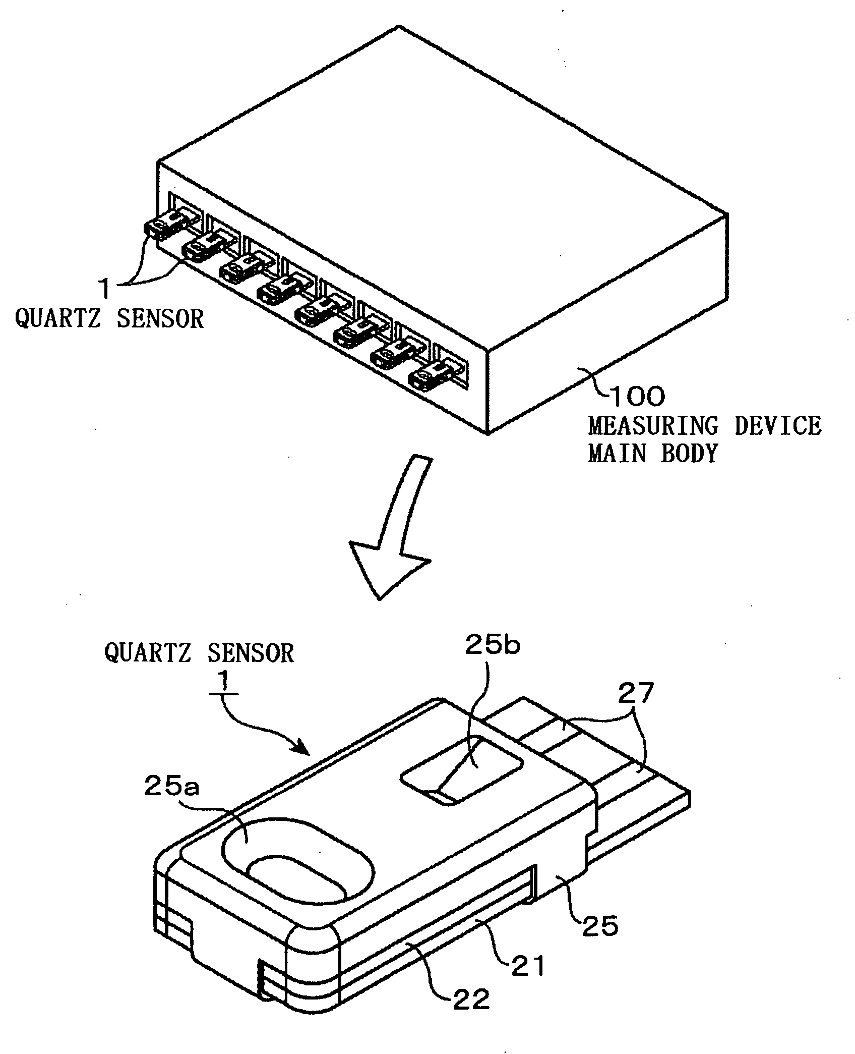
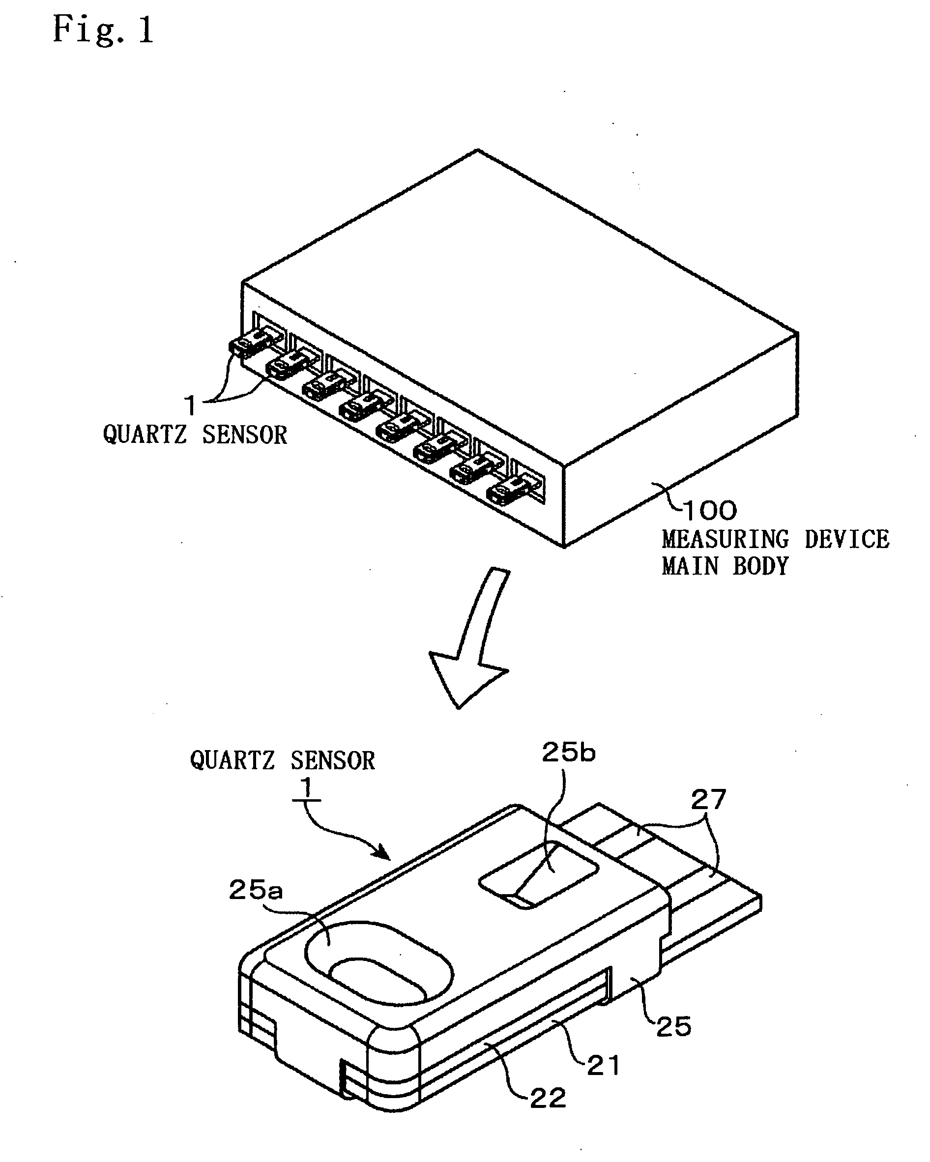
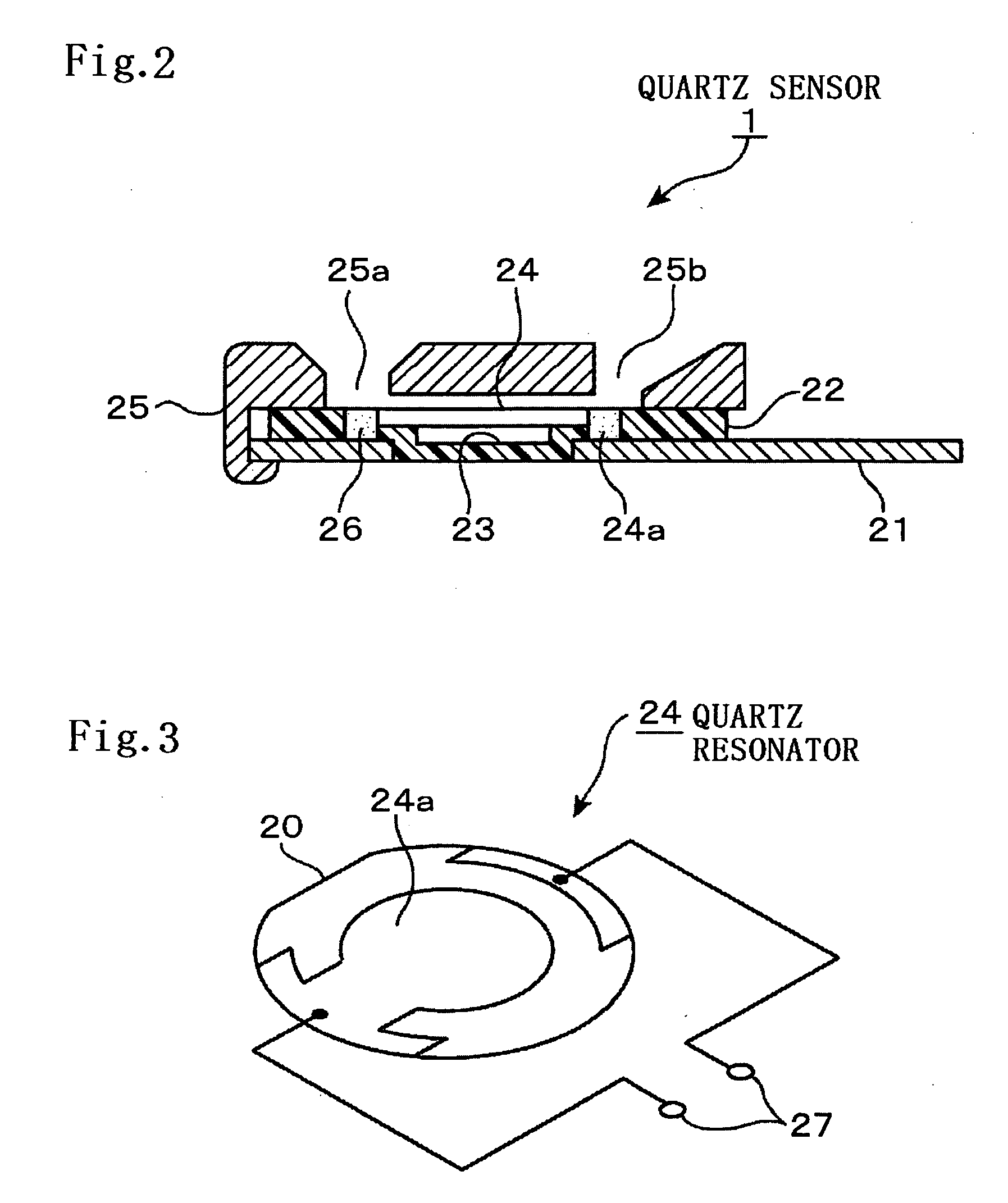
Sensing instrument

Inactive Publication Date: 2010-02-04
NIHON DEMPA KOGYO CO LTD
View PDF7 Cites 1 Cited by
  • Summary
  • Abstract
  • Description
  • Claims
  • Application Information

AI Technical Summary

Benefits of technology

[0015]According to the present invention, when the liquid comes into contact with the piezoelectric resonator, the equivalent series resistance of the piezoelectric resonator becomes high, but since the driving current for oscillating the piezoelectric resonator is set to 0.3 mA or less, it is possible to suppress the self-heating of the piezoelectric resonator

Problems solved by technology

The former requires an extremely high instrument cost and thus a considerably high analysis cost and takes a long period of time for analysis, and the latter is low in analysis precision, though requiring less instrument cost and analysis cost and taking a shorter period of time for analysis compared with the gas-chromatography mass spectrometer.
Incidentally, a sensing instrument using a quartz sensor, if not requiring very high measurement precision, is not difficult to manufacture, but if requiring high measurement precision, it is practically difficult to manufacture.
The reason is that it is very difficult to detect a minute frequency change accurately and in a short time, and besides the adsorption of a substance to be sensed, there are many disturbance factors for frequency fluctuation.
However, the higher the sensitivity of the frequenc

Method used


Image

  • Sensing instrument
  • Sensing instrument
  • Sensing instrument

Examples


Example

Experimental Example 1

[0046]The experiment was conducted in order to find a frequency-temperature characteristic of the quartz resonator 24, under various driving currents, and data obtained when the driving current was 10 mA among the obtained data was studied. FIG. 9 shows a difference between the frequency-temperature characteristic when the driving current is 10 mA and a reference frequency-temperature characteristic when the driving current is 0.1 mA. FIG. 10 shows the frequency-temperature characteristic when the driving current is 0.1 mA and the frequency-temperature characteristic when the driving current is 10 mA. It is understood from FIG. 9 that the frequency at 85° C. when the driving current is 10 mA is f1+0.7×10⁻⁶, where f1 is the frequency at 8520 C. when the driving current is 0.1 mA as shown in FIG. 10. The f1+0.7×10⁻⁶ frequency is detected at the temperature of (85+Δt)° C. when the driving current is 0.1 mA, while it is detected at the temperature of 85° C. when t...

Example

Experimental Example 2

Example 1-1

[0047]In the measurement of a substance to be sensed using the above-described sensing instrument, a predetermined amount of pure water was supplied into the quartz sensor 1, and the oscillation driving power was applied so that the driving current of the quartz piece 20 became 0.2 mA. Subsequently, a predetermined amount of a PBS solution (a phosphoric acid buffer solution) containing 100 μg / ml of a CRP antibody was injected into the pure water in the quartz sensor 1 while the 0.2 mA driving current was applied to the quartz piece 20. Then, states of the oscillation frequency of the quartz resonator 24 before and after the antigen-antibody reaction were observed. The states are shown in FIG. 11. Note that in this measurement, the quartz resonator 24 with a 9.176 MHz oscillation frequency is used.

Comparative Example 1-1

[0048]The substance to be sensed was measured with the same supply amounts of the pure water and the sample solution as those of the...

Example

Example 2-1

[0049]The substance to be sensed was measured with the same supply amount of the pure water and the same value of the driving current as those of the example 1-1, except that a predetermined amount of the PBS solution containing a 10 μg / ml CRP antibody was injected into the pure water in the quartz sensor 1. Then, states of the oscillation frequency of the quartz resonator 24 before and after the antigen-antibody reaction were observed. The states are shown in FIG. 12.

Comparative Example 2-1

[0050]The substance to be sensed was measured with the same supply amounts of the pure water and the sample solution as those of the example 2-1, except that the driving current was adjusted to 0.5 mA. Then, states of the oscillation frequency of the quartz resonator 24 before and after the antigen-antibody reaction were observed. The states are shown in FIG. 12.

[0051](Results and Discussion)

[0052]In FIG. 11 and FIG. 12, oscillation frequency f is taken on the vertical axis and time t ...


PUM


Abstract

It is an object of the present invention to provide a sensing instrument using a piezoelectric resonator such as a quartz resonator which changes in natural frequency when coming into contact with a liquid to adsorb a substance to be sensed in the liquid, the sensing instrument having a reduced adverse effect accompanying improvement in detection sensitivity precision of a frequency change.
The sensing instrument of the present invention includes: an oscillator circuit supplying a piezoelectric resonator with oscillation driving power for oscillating the piezoelectric resonator so as to set a driving current to 0.3 mA or less; and a measuring unit measuring a concentration of the substance to be sensed based on an oscillation output of the oscillator circuit. This structure can suppress self-heating of the piezoelectric resonator. Consequently, a change of the oscillation frequency of the piezoelectric oscillator is suppressed, which as a result enables accurate detection of a variation of the frequency due to the adsorption of the substance to be sensed.

Description

TECHNICAL FIELD[0001]The present invention relates to a sensing instrument which uses a piezoelectric resonator, for example, a quartz resonator having, on its front surface, an adsorption layer for adsorbing a substance to be sensed and changing in natural frequency when coming into contact with a liquid to adsorb the substance to be sensed in the liquid and which detects a variation of the natural frequency of the piezoelectric resonator to sense the substance to be sensed in the liquid.BACKGROUND ART[0002]As a method for sensing a trace substance, a sensing instrument using a quartz resonator has been known. This sensing instrument has a quartz sensor in which an adsorption layer for adsorbing a substance to be sensed is formed on a front surface of the quartz resonator, and measures the presence / absence or concentration of the substance to be sensed by utilizing the fact that when the quartz resonator, more particularly, the adsorption layer adsorbs the substance to be sensed, i...

Claims


Application Information

Patent Timeline
IPC IPC(8): G01N5/02
CPCG01N5/02
Inventor KOYAMA, MITSUAKI
Owner NIHON DEMPA KOGYO CO LTD
Why Eureka
Try Eureka