Arc resistant shutters

a technology of arc-resistant shutters and shutters, which is applied in the direction of insulated conductors, cables, plastic/resin/waxes insulators, etc., can solve the problems of affecting the service life of the cabinet, etc., to achieve simple and strong design, easy to make and use

Active Publication Date: 2015-12-24
SCHNEIDER ELECTRIC USA INC
View PDF10 Cites 12 Cited by
  • Summary
  • Abstract
  • Description
  • Claims
  • Application Information

AI Technical Summary

Benefits of technology

[0013]The shutter is a reinforced structure composed of an insulator material, which is a simple and strong design able to resist the destructive energy released during an arc flash. The insulator cap may be a coating of insulator material or it may be part of an insulator cover or sheath fit over the bus bar or bus bar extension and covering the free end thereof. The shutter assembly comprising the shutter and insulator cap, fits within the arc attenuating chamber of an individual phase, and is thus reliable while being easy to make and use.

Problems solved by technology

The making and breaking of connections and the handling of heavy currents in the area of connection between control devices like circuit interrupters (breakers), makes this area of the cabinet particularly susceptible to arcing.
The resulting arc flash has the potential to cause considerable damage, including arcing-induced erosion of the contacts and injury to operators.
Damage may be caused to the switchgear both by the explosion of the arc flash and by the heat radiating from the blast.

Method used


Image

  • Arc resistant shutters
  • Arc resistant shutters
  • Arc resistant shutters

Examples


Embodiment Construction

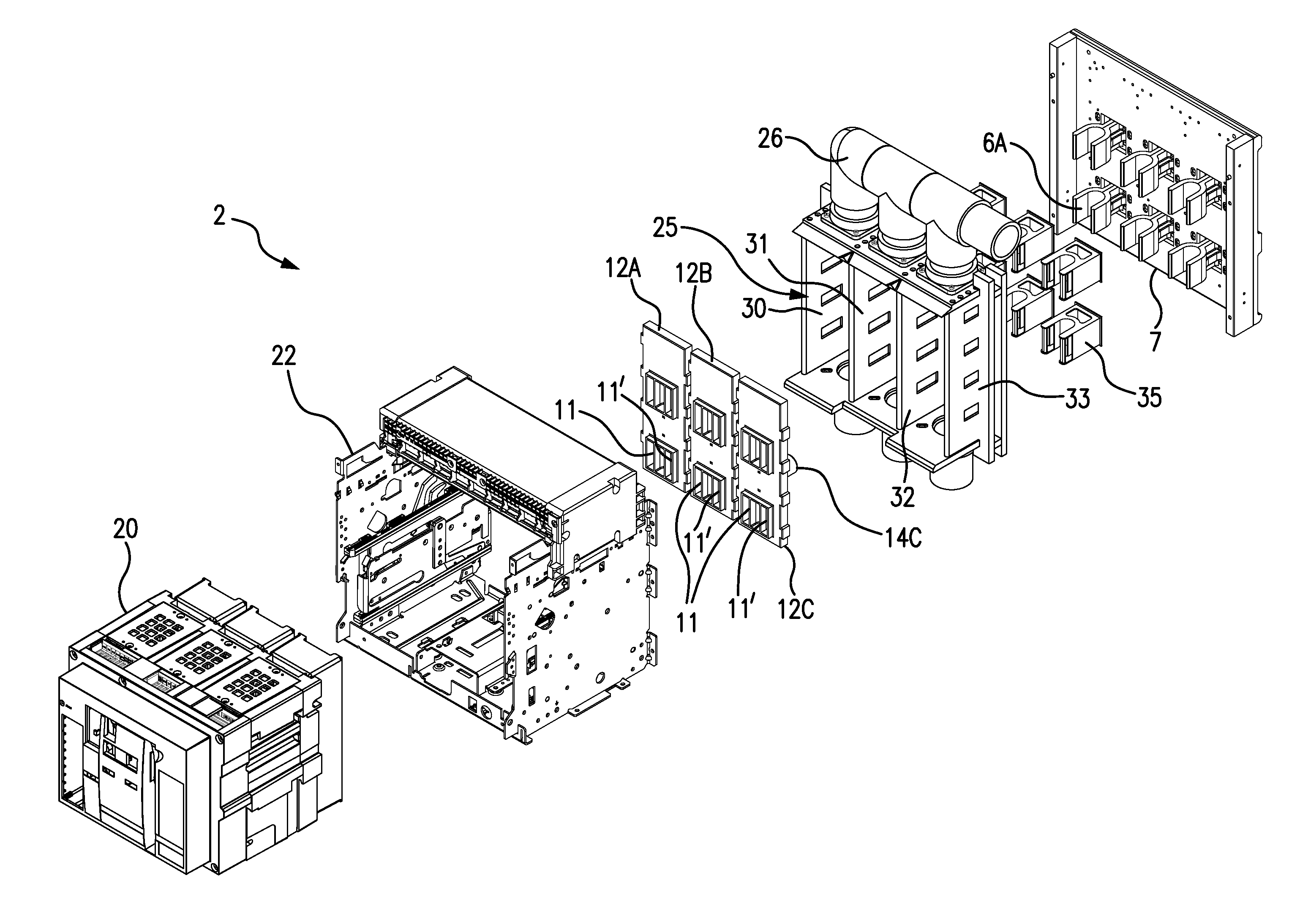
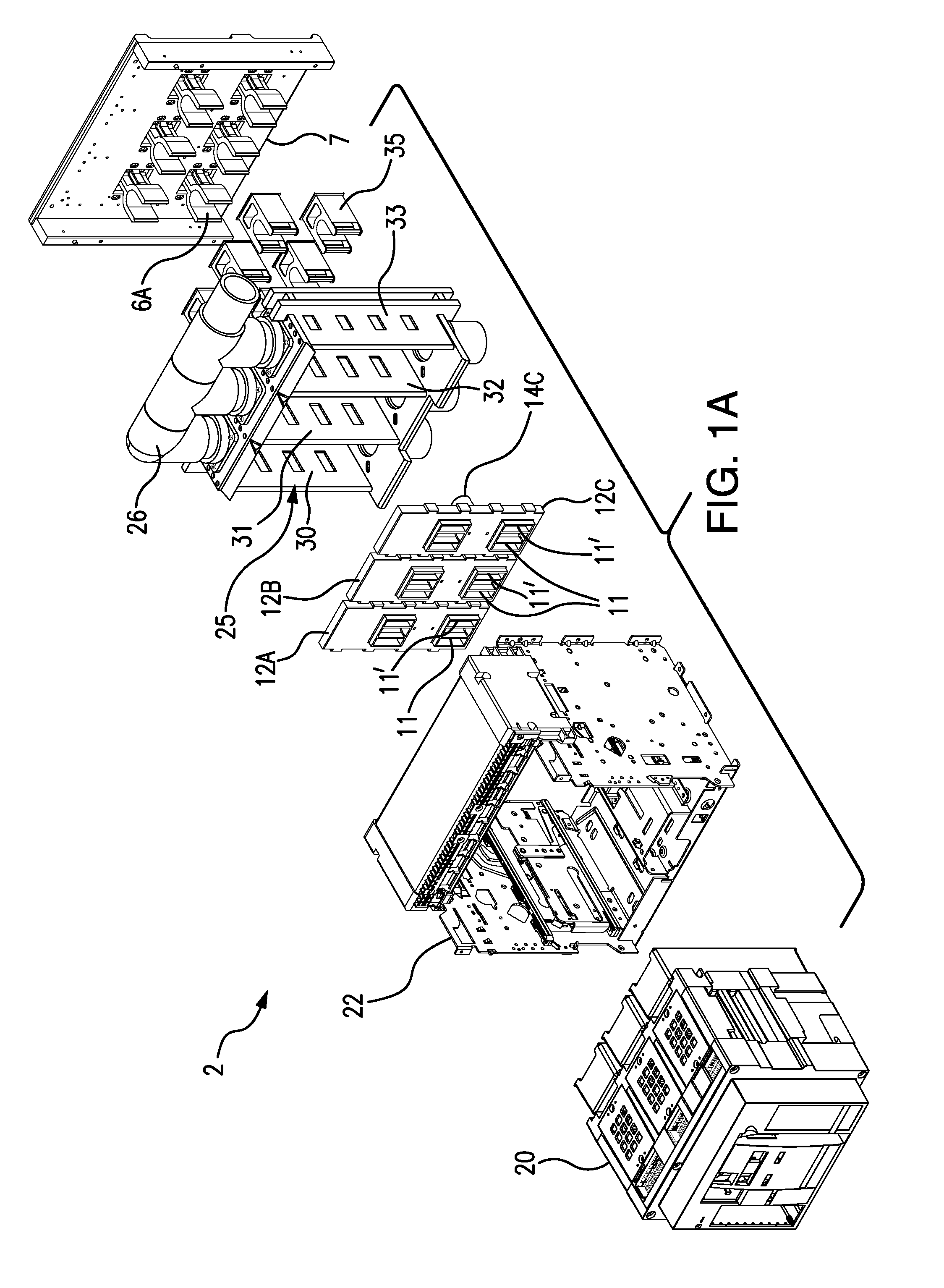
[0033]FIG. 1A is a front perspective, exploded view of from the right side of a draw out circuit breaker system 2, including a draw-out circuit breaker 20, a supporting cradle 22, a shutter assembly of independently movable, arc resistant shutters 12A, 12B, and 12C, an arrangement of phase barriers 30, 31, 32, and 33, an arrangement of sheaths 35 for bus bar extensions, an arrangement of bus bar extensions including the bus bar extension 6A, and a back-mold 7. The draw out circuit breaker system 2 may be typically installed in a switchgear cabinet (see, for example, FIG. 5) along with other electrical equipment and devices for distributing, controlling, and / or protecting electrical equipment. The supporting cradle 22 is for receiving the draw-out circuit breaker 20 that is movable in and out of contact with an electrical supply. Within the switchgear cabinet, the electrical supply may be received via one or more bus bars (not shown) having bus bar extensions, that extend towards the...


PUM

PropertyMeasurementUnit
forceaaaaaaaaaa
insulatoraaaaaaaaaa
phaseaaaaaaaaaa

Abstract

A connection system for connecting electrical devices to busses within a switchgear cabinet includes an independently movable shutter that slides along a bus bar, the shutter covering access to the bus bar in a disconnected position and allowing access in a connected position. The bus bar has an insulator cap covering its free end. The shutter is mounted to a spring-biased support. The shutter has an opening through which the bus bar passes. The shutter slides along the bus bar backwardly away from the insulator cap, in the connected position. The shutter slides forwardly along the bus bar toward the insulator cap, in the disconnected position. The insulator cap fits closely within the opening in the shutter to prevent access to the bus bar when in the disconnected position. The shutter can fit within arc attenuating phase barriers surrounding each bus bar and be constructed to be arc resistant.

Description

BACKGROUND OF THE INVENTION[0001]1. Field of the Invention[0002]The invention disclosed relates to arc resistant electrical distribution equipment.[0003]2. Discussion of the Related Art[0004]Circuit breakers used in switchgear cabinets are often constructed in a draw-out configuration that allows breaker insertion or removal by moving the breaker in a cradle assembly. The draw-out breakers have a connected position in which clusters, i.e. connectors having opposing stacks of plate-like fingers, engage bus bar extensions of bus bars in the switchgear cabinet. In a disconnected position, including the test position in some types of breakers, the clusters are disconnected from the bus bar extensions. To cover access to, and prevent inadvertent contact with, the bus bar extensions when the breaker is in the disconnected position, shutter systems have been utilized across a back plane of the cradle assembly. One shutter system includes sliding panels that protect all breaker phases at th...

Claims


Application Information

Patent Timeline
Patent Type & Authority Applications(United States)
IPC IPC(8): H02B1/14H02B1/21H01B17/42H02B1/30
CPCH01H9/22H01B17/42H02B1/14H02B11/24H02B1/30H02B11/04H02B1/21H02B1/36
Inventor FABER, TIMWOODSON, CAMERONROMERO LEGORRETA, GERMAN
Owner SCHNEIDER ELECTRIC USA INC
Why Eureka
Try Eureka