Passive arc control with sequestered phases in a vertical bus system of a motor control center

a technology of motor control center and arc control, which is applied in the direction of switchgear details, substation/switching arrangement casings, manufacturing tools, etc., can solve the problems of affecting the service life of the switchgear

Active Publication Date: 2017-08-17
SCHNEIDER ELECTRIC USA INC
View PDF13 Cites 3 Cited by
  • Summary
  • Abstract
  • Description
  • Claims
  • Application Information

AI Technical Summary

Benefits of technology

[0008]Example embodiments of the invention minimize the potential for harm to equipment and people by containing and redirecting the arc energy out from the MCC.
[0013]The shutter assembly provides a physical barrier to debris, tools, and operator fingers, denying access to the vertical bus bar when the device, i.e. breaker, is disconnected from the vertical bus bar. The passive arc control system of the present invention may prevent hazardous arc flash exposure to personnel even with the front door of the motor control center open or the motor control units in their unconnected positions.
[0016]The shutter is a reinforced structure composed of an insulator material, which is a simple and strong design able to resist the destructive energy released during an arc flash. The shutter assembly comprising the shutter and insulator cap, fits within the arc attenuating box of an individual phase, and is thus reliable while being easy to make and use.
[0019]The motor control center may have additional rows of arc attenuating boxes, with each arc attenuating box surrounding an individual one of the vertical bus bar phases. Each arc attenuating box in the additional rows may be open at its top and bottom to form a chimney along a respective vertical bus bar phase, the chimney being aligned with the chimney of an arc attenuating box of other rows of arc attenuating boxes, to provide directed venting of arc flash energy and gases out of the motor control center.

Problems solved by technology

The making and breaking of connections and the handling of heavy currents in the area of connection between control devices like circuit interrupters (breakers), makes this area of the cabinet particularly susceptible to arcing.
The resulting arc flash has the potential to cause considerable damage, including arcing-induced erosion of the contacts and injury to operators.
Damage may be caused to the switchgear both by the explosion of the arc flash and by the heat radiating from the blast.

Method used


Image

  • Passive arc control with sequestered phases in a vertical bus system of a motor control center
  • Passive arc control with sequestered phases in a vertical bus system of a motor control center
  • Passive arc control with sequestered phases in a vertical bus system of a motor control center

Examples


Embodiment Construction

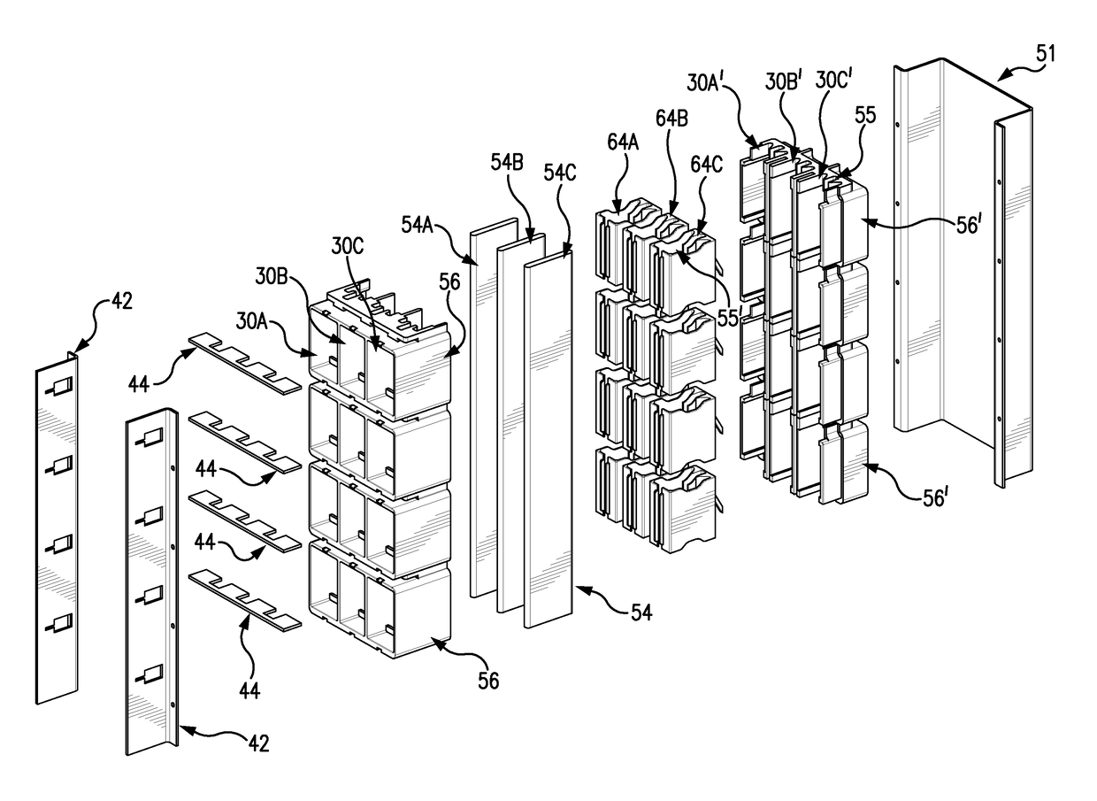
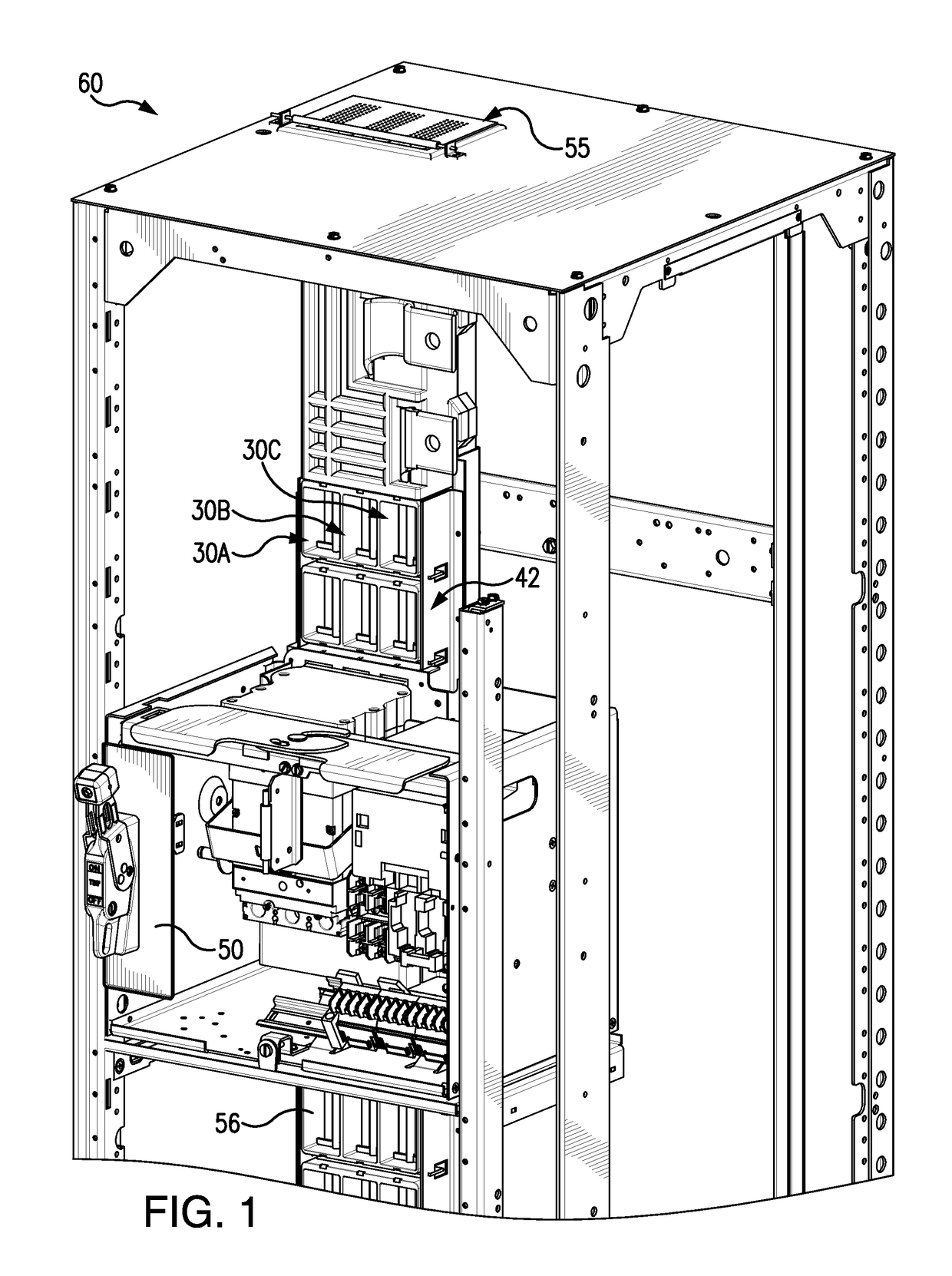
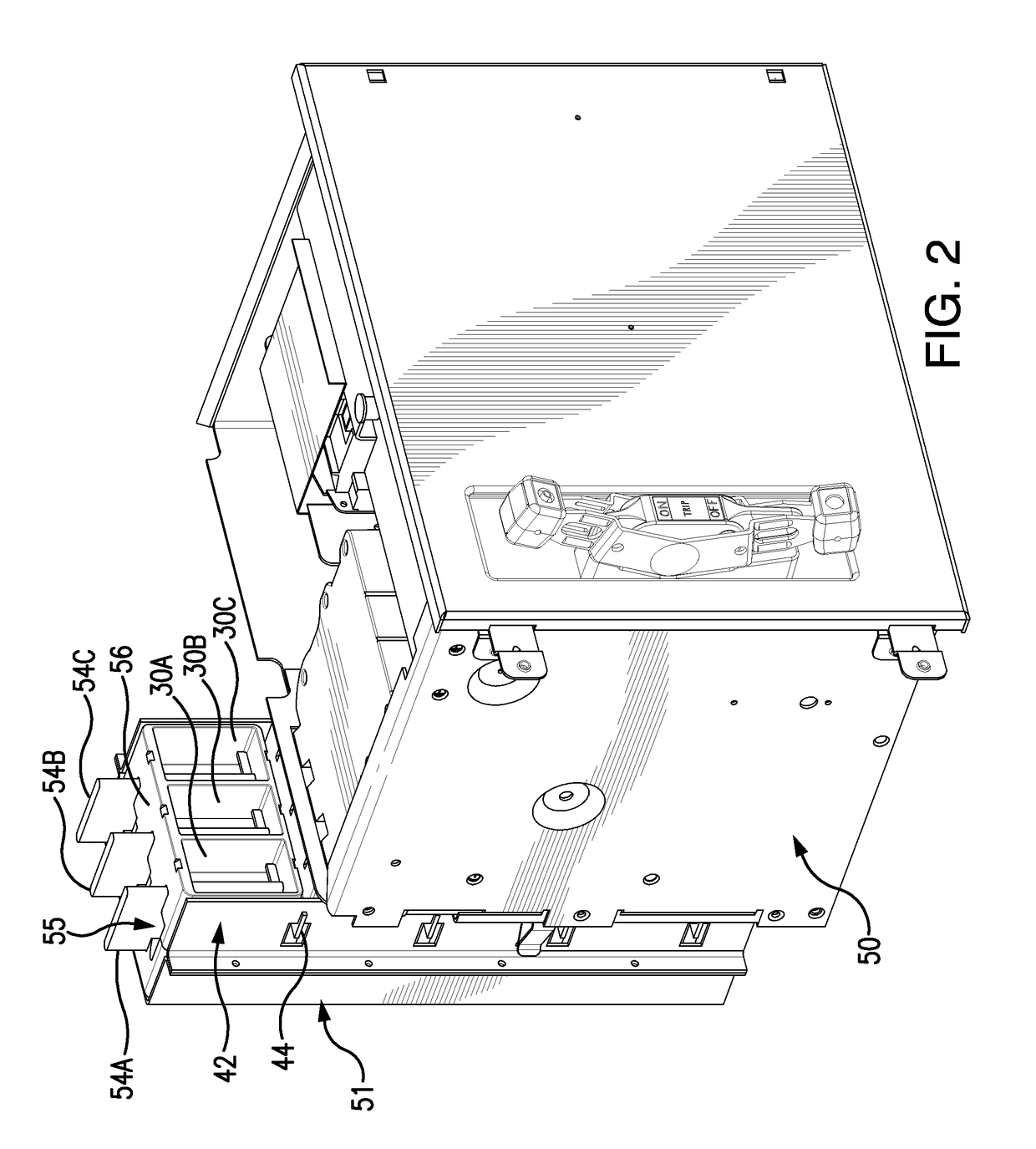
[0029]FIG. 1 is a front perspective view from the right side, of a motor control center (MCC) cabinet 60 into which has been inserted a motor control unit 50 for connection to three vertical bus bar phases 54A, 54B, and 54C (shown in FIGS. 2 and 3) via a front portion 30A, 30B, and 30C of three arc attenuating boxes A, B, and C (shown in FIG. 7) supported in the MCC cabinet 60 by a front bus frame comprising a vertical support 42. Each of the front portions 30A, 30B, and 30C of the three arc attenuating boxes A, B, and C forms part of a chimney 55 along the respective three vertical bus bar phases 54A, 54B, and 54C, to provide directed venting of arc flash energy and gases out of the MCC cabinet 60. The motor control unit 50 is not normally connected to the bus bars when the unit is initially racked into the MCC cabinet 60. The motor control unit has a handle-cam mechanism (not shown) to rack-in the unit into the MCC cabinet, which mechanically locks the motor control unit into plac...


PUM

PropertyMeasurementUnit
flash energyaaaaaaaaaa
forceaaaaaaaaaa
poweraaaaaaaaaa

Abstract

A passive arc control system for a motor control center 60 includes an arc attenuating box having sides separating adjacent vertical bus bar phases 54, providing a physical barrier to arc flash energy. The box is open at its top and bottom forming a chimney 55. A shutter assembly for each box includes an insulator cap 62 on a free end of the bus bar and an independently moveable, box-shaped shutter 64 that slides along the bus bar away from the insulator cap, when a device is connected to the bus bar. The shutter has an opening 65 through which the bus bar passes when the device is connected to the bus bar and an opening 55′ aligned with the box's chimney. The arc control system provides a high degree of arc protection for personnel working around open motor control centers and is highly modular and easy to construct.

Description

[0001]This is a Divisional Application of co-pending U.S. patent application Ser. No. 14 / 557,817, filed Dec. 2, 2014, of which the entire disclosure is incorporated herein by reference. Co-pending U.S. patent application Ser. No. 14 / 557,817 is a Continuation-In-Part (CIP) of U.S. patent application Ser. No. 14 / 310,660, filed Jun. 20, 2014, now U.S. Pat. No. 9,312,668, which issued on Apr. 12, 2016, of which the entire disclosure is incorporated herein by reference. The Applicant claims benefit of the priority filing dates of the co-pending U.S. patent application Ser. No. 14 / 557,817 and the U.S. patent application Ser. No. 14 / 310,660 under 35 U.S.C. 120, for claims made in the present U.S. Patent Application, which are directed to subject matter disclosed in the respective co-pending U.S. patent application Ser. No. 14 / 557,817 and U.S. patent application Ser. No. 14 / 310,660.BACKGROUND OF THE INVENTION[0002]1. Field of the Invention[0003]The invention disclosed relates to arc resista...

Claims


Application Information

Patent Timeline
Patent Type & Authority Applications(United States)
IPC IPC(8): H02B1/21H02B11/24B23K9/073H01B17/42H02B1/14H02B1/30H01H9/22H02B11/04
CPCH02B1/21H01H9/22H02B11/24B23K9/073H01B17/42H02B1/14H02B1/30H02B11/04
Inventor ROMERO LEGORRETA, GERMANFABER, TIMRICHARDS, WALTER J.
Owner SCHNEIDER ELECTRIC USA INC
Why Eureka
Try Eureka