Shielding apparatus, shielding method and demagnetizing for measuring magnetic field

a shielding apparatus and magnetic field technology, applied in the direction of magnetic variables, magnetic bodies, instruments, etc., can solve the problems of increasing the manufacturing cost of the plurality of coils, the inability to precisely measure the subtle magnetic field of the sample provided in the measurement space, and the inability to insert a plurality of coils, so as to minimize the effect of the eddy current generated by the magnetic field

Active Publication Date: 2016-01-14
KOREA RES INST OF STANDARDS & SCI
View PDF2 Cites 4 Cited by
  • Summary
  • Abstract
  • Description
  • Claims
  • Application Information

AI Technical Summary

Benefits of technology

[0024]Therefore, according to an embodiment of the present invention as described above, it is effective in that since a high-conductivity metal layer of each shield wall is configured to be partitioned into a plurality of different segments, flow of eddy current induced at the high-conductivity metal layer by an excitation magnetic field generated inside a shield room can be cut off, and thus the effect of the eddy current generated by the magnetic field can be minimized.
[0025]In addition, according to another embodiment of the present invention, it is effective in that since a plurality of coil units formed by winding a coil to penetrate each corner of a high-permeability soft magnetic layer configuring the shield room is provided, the front surface of the high-permeability soft magnetic layer configuring the shield room is demagnetized by applying current to the coil units by a power supply unit.

Problems solved by technology

That is, if an induced magnetic field is generated at the shield wall, the eddy current flows along the closed circuit for an extended period of time, and thus there is a problem in that a subtle magnetic field of the sample provided in the measurement space cannot be measured precisely due to the strong magnetic field generated by the continuous eddy current.
However, such a method has a problem in that it is difficult to insert a plurality of coils inside the shield room in manufacturing the shield apparatus, and manufacturing cost thereof is increased.

Method used


Image

  • Shielding apparatus, shielding method and demagnetizing for measuring magnetic field
  • Shielding apparatus, shielding method and demagnetizing for measuring magnetic field
  • Shielding apparatus, shielding method and demagnetizing for measuring magnetic field

Examples


first embodiment

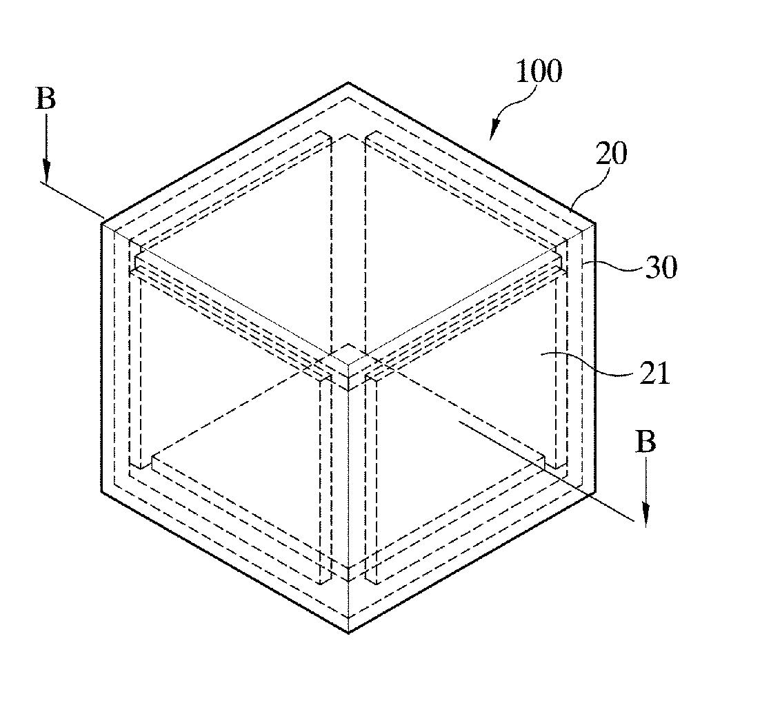
[0062]The shield apparatus 100 according to the present invention is sealed by an outer shield wall 40 and a shield wall 40 provided at an inner side, which has a high-conductivity metal layer 21 partitioned into a plurality of segments, and has a measurement space 7 inside thereof. Accordingly, a sample is put into the measurement space 7, and a subtle magnetic field generated from the sample is measured by a precise magnetic sensor provided in the measurement space 7. Since such a partitioned high-conductivity metal layer 21 is included, flow of eddy current induced by a strong excitation magnetic field, which is generated by a magnetic field generation apparatus for exciting the sample provided inside the measurement space 7, is cut off.

[0063]In a first embodiment of the present invention, a material of high conductivity having a high-frequency shield property is used for the high-conductivity metal layer 20 and the partitioned high-conductivity metal layer 21. For example, they ...

second embodiment

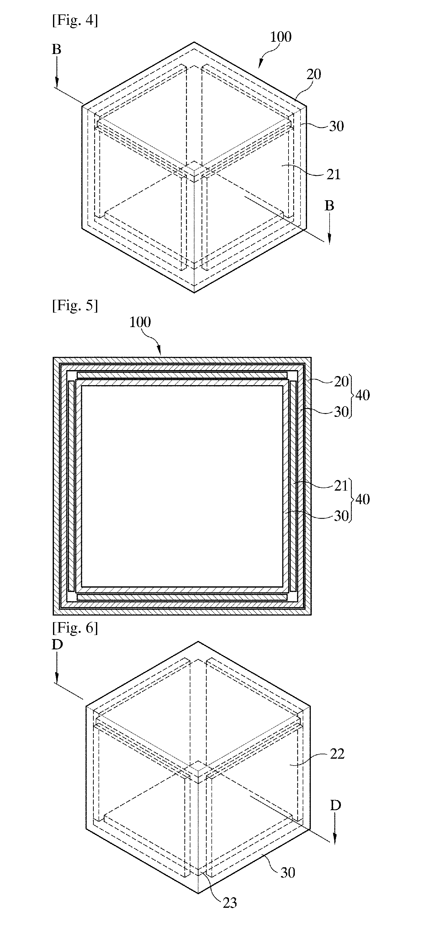
[0067]As shown in FIGS. 6 and 7, in the shield apparatus 100 according to the present invention, the outermost shield wall 40 has a high-conductivity metal layer 20 and a high-permeability soft magnetic layer 30 which are completely sealed, and the shield wall 40 installed in the middle has a first high-conductivity metal layer 22 partitioned into three segments respectively having a cross section of a “” shape and a sealed high-permeability soft magnetic layer 30 installed to be spaced apart from the first partitioned high-conductivity metal layer 22 by a predetermined distance toward inside thereof. In addition, the innermost shield wall 40 has a second high-conductivity metal layer 23 partitioned into six segments respectively having a cross section of a “” shape and a sealed high-permeability soft magnetic layer 30 installed to be spaced apart from the second partitioned high-conductivity metal layer 23 by a predetermined distance toward inside thereof. Accordingly, the high-con...


PUM


Abstract

The present invention relates to a shield apparatus and a shield method for measuring a subtle magnetic field. More specifically, the present invention relates to a shield apparatus having a precise magnetic sensor therein, for shielding an external magnetic field in a subtle magnetic field measurement apparatus including a magnetic field generation apparatus for exciting a sample, the shield apparatus for measuring a subtle magnetic field, including: a shield wall provided with a high-conductivity metal layer of high conductivity being partitioned into a plurality of segments and having a high-frequency shield property and a closed high-permeability soft magnetic layer spaced apart from the high-conductivity metal layer by a predetermined distance, so as to seal a measurement space.

Description

TECHNICAL FIELD[0001]The present invention relates to a shield apparatus and a shield method for measuring a subtle magnetic field. More specifically, the present invention relates to a shield apparatus and a shield method for measuring a subtle magnetic field, in which a shield wall configuring the shield apparatus is formed as a high-conductivity metal layer partitioned into a plurality of segments, and a plurality of coil units respectively pen-etrating a corner is provided in each shield wall, and thus an eddy current flowing along the shield apparatus can be prevented, and the shield wall can be demagnetized.BACKGROUND ART[0002]A shield room configuring a shield apparatus effectively shields a high-frequency magnetic field, as well as a direct current (DC) low-frequency magnetic field, based on both a magnetic field shield effect obtained using a soft magnetic material of high permeability and an eddy current shield effect obtained using a metal of high electrical conductivity....

Claims


Application Information

Patent Timeline
Patent Type & Authority Applications(United States)
IPC IPC(8): G01R33/00G01R33/025
CPCG01R33/025G01R33/0076H01F13/003H05K9/0069
Inventor KIM, KI WOONGLEE, YONG HOYU, KWON KYULEE, SEONG-JOO
Owner KOREA RES INST OF STANDARDS & SCI
Why Eureka
Try Eureka