Pedal device for electronic percussion instrument

Active Publication Date: 2016-01-14
ROLAND CORPORATION
View PDF17 Cites 7 Cited by
  • Summary
  • Abstract
  • Description
  • Claims
  • Application Information

AI Technical Summary

Benefits of technology

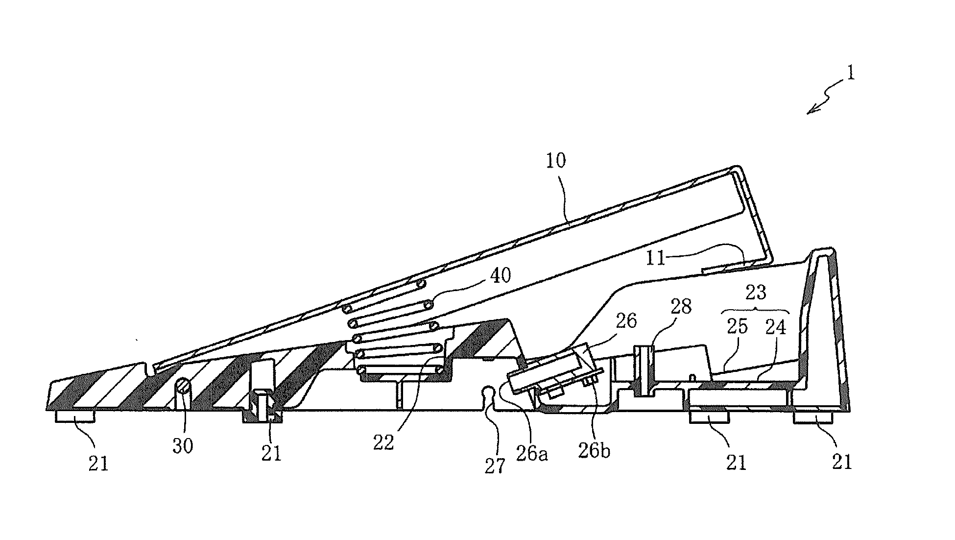
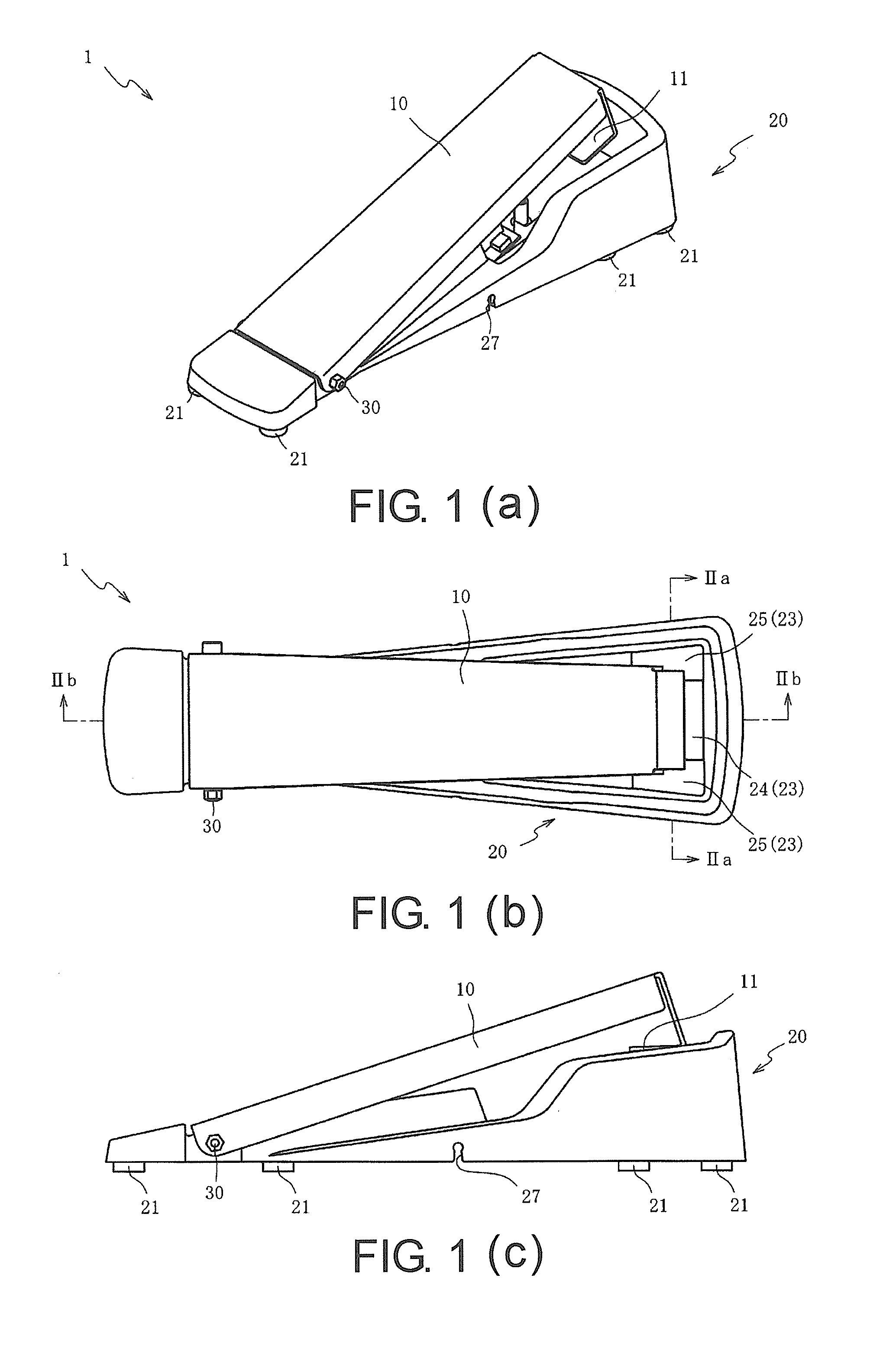
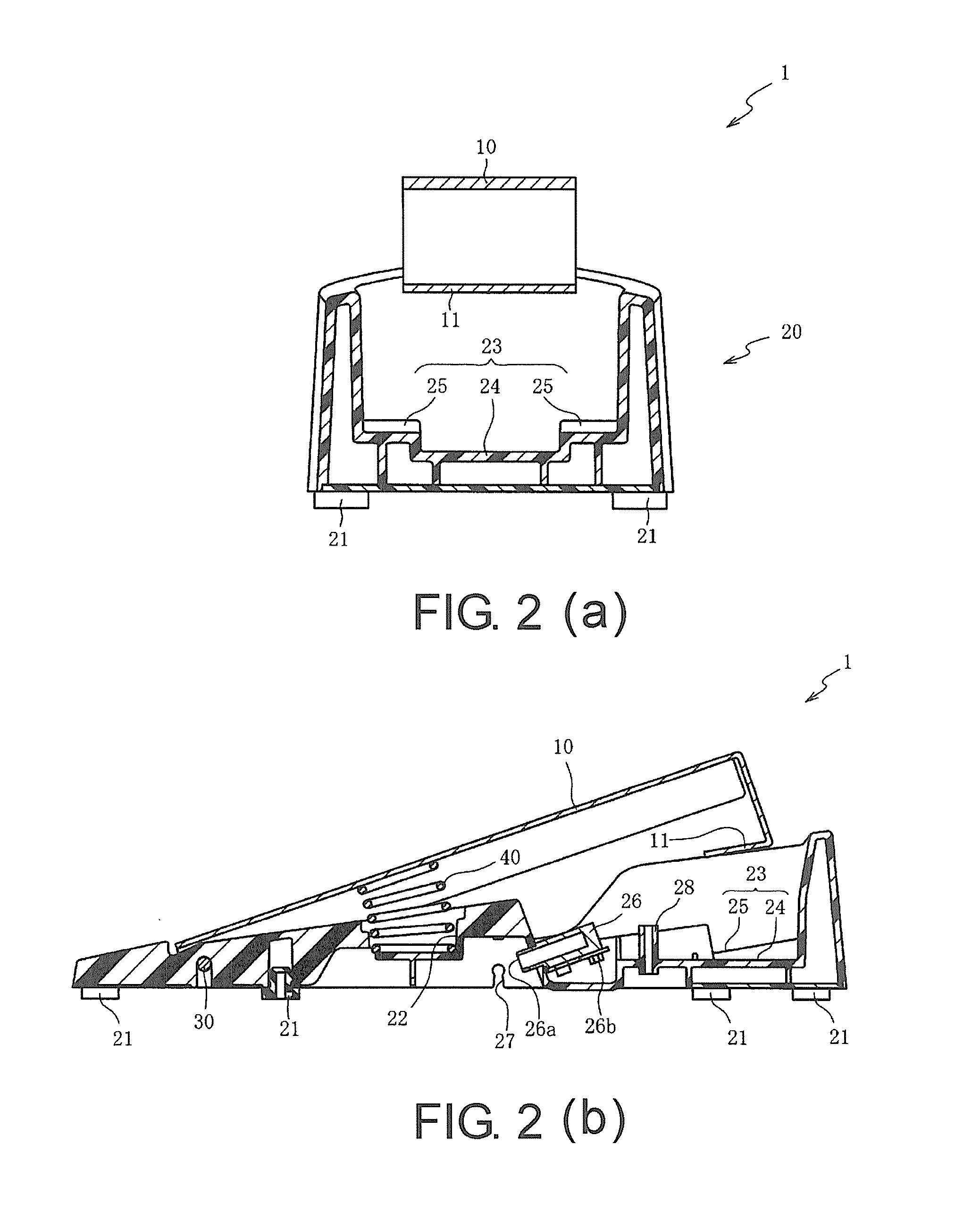
[0021]According to another embodiment of the invention, in the pedal device for the electronic percussion instrument, when the base is placed on the floor, the second portion supports the second pressed part in a state that the second pressed part inclines relative to the floor. In this way, the pressing force the pressing part applies on the second pressed part can be easily applied in the thickness direction of the second pressed part. Thus, in addition to the aforementioned effects, the shearing force applied on the second pressed part can be reduced to prevent the second pressed part from damaging soon. Furthermore, the pressing force from the pressing part can be transferred to the second pressed part efficiently. Consequently, the rotation of the pedal can be accurately detected by the second sensor.
[0022]According to another embodiment of the invention, in the pedal device for the electronic percussion instrument, when the base is placed on the floor, the second portion inclines relative to the floor. In this situation, the pressing force the pressing part applies on the second pressed part can be easily applied in a direction substantially perpendicular to the second portion. The second pressed part can be compressed efficiently in the thickness direction thereof between the pressing part and the second portion. Thus, in addition to the aforementioned effects, the shearing force applied

Problems solved by technology

As a result, compared with the second sensor, the first sensor has l

Method used


Image

  • Pedal device for electronic percussion instrument
  • Pedal device for electronic percussion instrument
  • Pedal device for electronic percussion instrument

Examples


Example

[0123]Hereinafter, the second embodiment is described with reference to FIG. 7(a) and FIG. 7(b). In the first embodiment, the second portions 25 are located above the first portion 24. In contrast thereto, in the second embodiment, the second portions 225 are located below the first portion 24. The same reference numerals are assigned to denote parts the same as those in the first embodiment. Thus, detailed descriptions thereof are omitted hereinafter.

[0124]FIG. 7(a) is a cross-sectional view of a pedal device 202 for electronic hi-hat, which uses a pedal device 201 of the second embodiment. FIG. 7(b) is a cross-sectional view of a pedal device 203 for electronic bass drum, which uses the pedal device 201. FIG. 7(c) is a cross-sectional view of the pedal device 203 for electronic bass drum. The cross-sectional views of FIG. 7(a) and FIG. 7(b) correspond to FIG. 2(a). The cross-sectional view of FIG. 7(c) corresponds to FIG. 6(c). FIG. 7(c) illustrates a state where the pedal 10 is s...

Example

[0142]According to the first embodiment, the second portion 25 of the support part 23 is located closer to the pressing part 11 than the first portion 24. According to the second embodiment, the first portion 24 of the support part 223 is located closer to the pressing part 11 than the second portion 225. However, the support part may be formed with a flat surface such that the distance from the second portion to the pressing part 11 is equal to the distance from the first portion 24 to the pressing part 11.

[0143]According to the second embodiment, the second pressed part 61 bridges the second portions 266 through the restricting parts 266 and displacement of the plate 64 is restricted by the restricting parts 266, so as to separate the second sensor 62 from the first portion 24 and prevent the first portion 24 from contacting the second sensor 62. However, the thickness dimension of the portion of the plate facing the upper surface of the second portion 225 may also be increased to...


PUM


Abstract

A pedal device for an electronic percussion instrument is provided, wherein first and second detection means for detecting a rotation of a pedal by different methods are alternatively disposed in a base. The pedal has a pressing part on a lower surface side. The base includes a first portion located under the pressing part for supporting the first detection means, and a second portion located around the first portion for supporting the second detection means. The first portion supports the first detection means such that a first pressed part of the first detection means is disposed on a displacement trajectory of the pressing part that displaces with the rotation of the pedal, and the second portion disposes the second detection means such that a second pressed part of the second detection means is disposed on the displacement trajectory of the pressing part.

Description

CROSS-REFERENCE TO RELATED APPLICATIONS[0001]This application claims the priority benefit of Japan application serial no. 2014-141830, filed on Jul. 9, 2014. The entirety of the above-mentioned patent application is hereby incorporated by reference herein and made a part of this specification.BACKGROUND OF THE INVENTION[0002]1. Field of the Invention[0003]The invention relates to a pedal device for an electronic percussion instrument. In particular, the invention relates to a pedal device for an electronic percussion instrument, which is capable of accurately detecting rotation of a pedal and achieves part commonality.[0004]2. Description of Related Art[0005]Among pedal devices that have a pedal configured to rotate when stepped by the player, some pedal devices simulate hi-hat or bass drum to be used in an electronic percussion instrument with a detection means for detecting rotation of the pedal.[0006]The pedal device for the electronic percussion instrument that simulates hi-hat ...

Claims


Application Information

Patent Timeline
IPC IPC(8): G10D13/00
CPCG10D13/006G10D13/02G10H1/348G10H2250/435G10D13/11
Inventor MORI, YOSHIAKI
Owner ROLAND CORPORATION
Why Eureka
Try Eureka