
Method of correcting measurement error of shape measuring apparatus, and shape measuring apparatus

Active Publication Date: 2016-01-21
MITUTOYO CORP
View PDF11 Cites 14 Cited by
  • Summary
  • Abstract
  • Description
  • Claims
  • Application Information

AI Technical Summary

Benefits of technology

The present invention allows for measuring angles by using a stylus and calculating a correction amount based on the angle formed between the stylus and the object being measured. This results in a more accurate measurement, regardless of the angle formed between the stylus and the object. Overall, this improves the accuracy of measurements.

Problems solved by technology

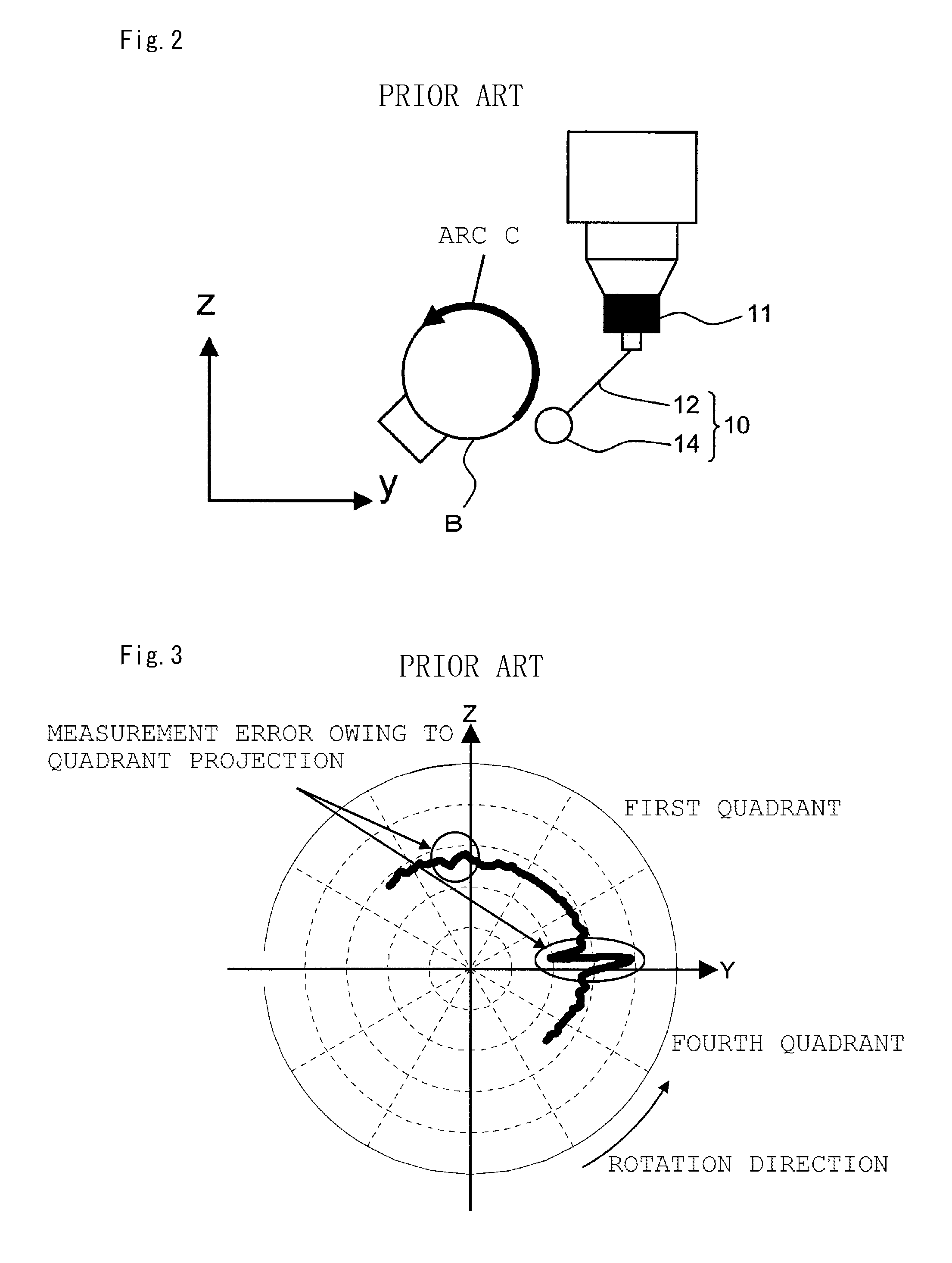
A measurement error due to the quadrant projection at the time of switching from a fourth quadrant to a first quadrant is especially prominent.
This is an error caused by the quadrant projection produced by a backlash and the like in reversing movement of the scanning probe 10.

Method used


Image

  • Method of correcting measurement error of shape measuring apparatus, and shape measuring apparatus
  • Method of correcting measurement error of shape measuring apparatus, and shape measuring apparatus
  • Method of correcting measurement error of shape measuring apparatus, and shape measuring apparatus

Examples


Embodiment Construction

[0045]Embodiments of the present invention will be described below in detail with reference to the drawings. Note that, the present invention is not limited to descriptions of the below embodiments and practical examples. Components of the embodiments and the practical examples described below contain what is easily assumed by those skilled in the art, what is substantially the same, and what is in a so-called equivalent scope. Moreover, the components disclosed in the embodiments and the practical examples described below may be appropriately combined with each other or appropriately selectively used.

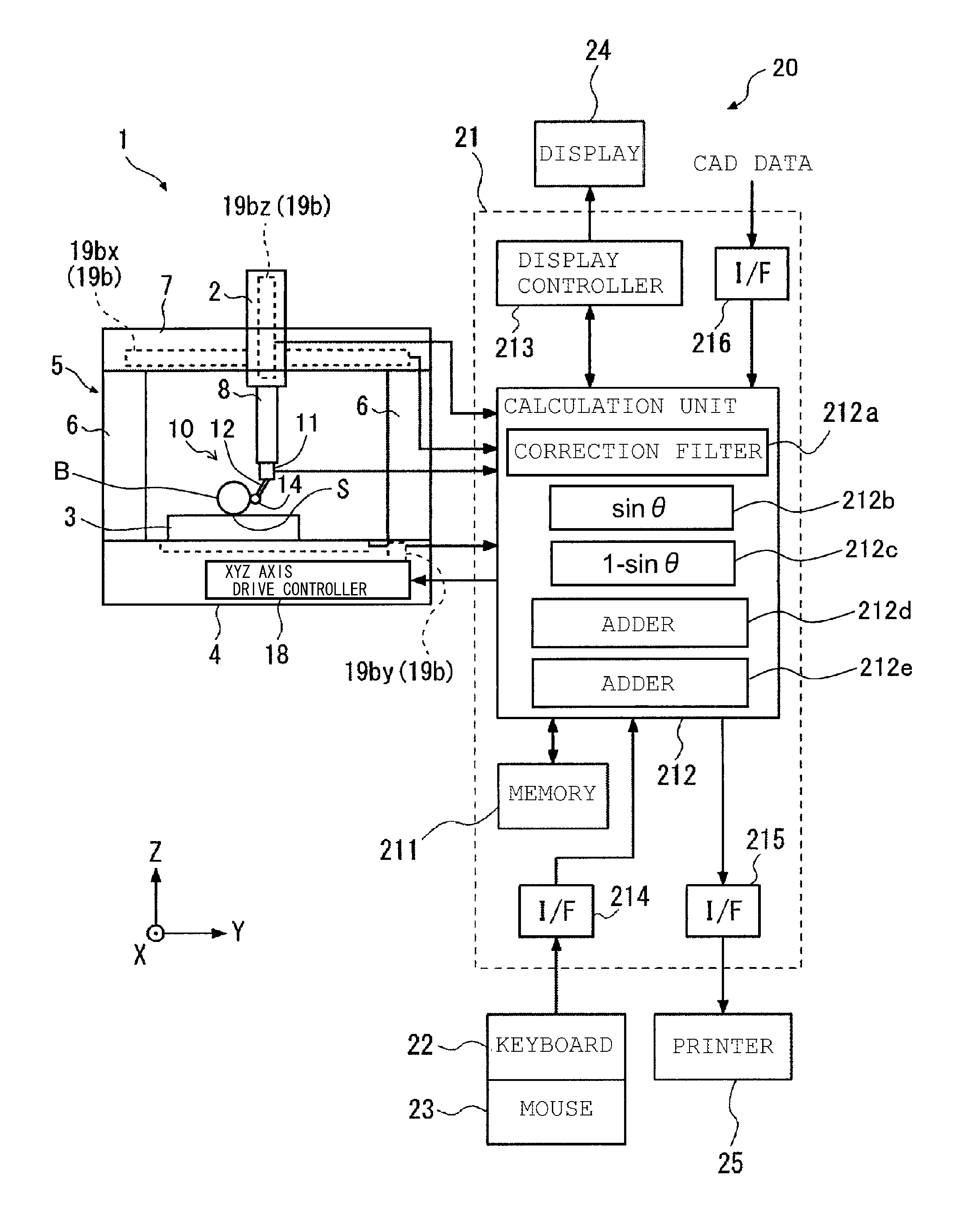
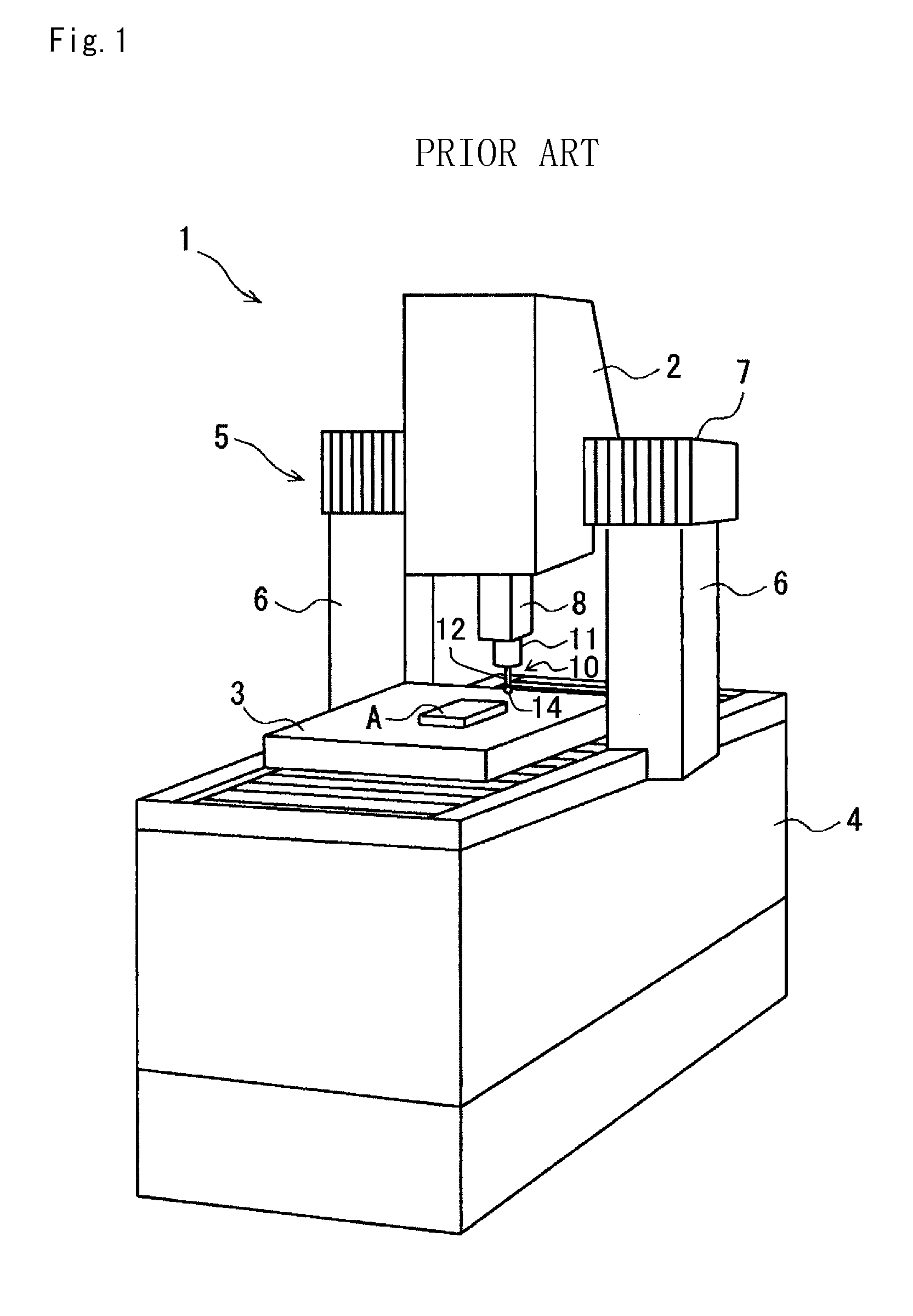
[0046]As shown in FIGS. 1 and 6, a shape measuring apparatus includes a three-dimensional measuring machine 1 and a computer 20 that are connected to each other through a not-shown cable.

[0047]The three-dimensional measuring machine 1 is provided with a base 4 installed on a floor or the like, and a support frame 5 in the shape of a gate erected on the base 4. The base 4 has a movable ...


PUM


Abstract

In a shape measuring apparatus having a scanning probe to perform scanning measurement using a tip ball provided at an end of a stylus with the tip ball being in contact with an object to be measured, a tip ball displacement detector detects a displacement of the tip ball of the scanning probe, a displacement of a moving mechanism that relatively moves the object to be measured and the scanning probe is detected, and an angle formed by a contact direction of the tip ball with the object to be measured and an axial direction of the stylus is calculated. The displacement of the tip ball that is detected by the tip ball displacement detector is corrected on the basis of the angle, and a corrected value of the displacement is outputted. The corrected value is added to the displacement of the moving mechanism to calculate a measurement value.

Description

CROSS-REFERENCE TO RELATED APPLICATION[0001]The disclosure of Japanese Patent Application No. 2014-148333 filed on Jul. 18, 2014 including specifications, drawings and claims is incorporated herein by reference in its entirety.TECHNICAL FIELD[0002]The present invention relates to a method of correcting a measurement error of a shape measuring apparatus, and a shape measuring apparatus. In particular, the present invention relates to a method of correcting a measurement error of a shape measuring apparatus when performing scanning measurement by means of the shape measuring apparatus provided with a scanning probe, which is suitably used in a three-dimensional coordinate measuring machine (also simply called three-dimensional measuring machine), and also relates to a shape measuring apparatus.BACKGROUND ART[0003]At present, to examine the processing accuracy and the like of a three-dimensional product, shape measuring apparatuses having a three-dimensional measuring machine 1 as show...

Claims


Application Information

Patent Timeline
IPC IPC(8): G01B21/04
CPCG01B21/045G01B5/008
Inventor NAKAGAWA, HIDEYUKIISHIKAWA, NOBUHIRO
Owner MITUTOYO CORP
Learn More