Systems and methods for recognizing objects in radar imagery

a radar imagery and object recognition technology, applied in the field of systems and methods for recognizing objects in radar imagery, can solve the problems of inability to successfully apply coherent active sensing modalities like sar, deep learning techniques like convolutional neural networks, etc., to improve historical speed and accuracy performance limitations, high performance, and low power gpu

Active Publication Date: 2016-01-21
GENERAL DYNAMICS MISSION SYST INC
View PDF7 Cites 168 Cited by
  • Summary
  • Abstract
  • Description
  • Claims
  • Application Information

AI Technical Summary

Benefits of technology

[0015]Embodiments of the present invention are directed to providing innovative advances to object recognition algorithms for SAR sensors on airborne vehicles. Specifically, embodiments of the invention receive a data stream from SAR sensors and use a deep neural network (“DNN”) to convert the received data into a set of semantic labels, where each semantic label corresponds to an object in the SAR data stream that the DNN has identified. Processing units running the DNN are collocated onboard an airborne vehicle along with the SAR sensor(s). The processing units are configured with powerful, high-speed graphics processing units (“CPUs”) or field-programmable gate arrays (“FPGAs”) that are low in size, weight, and power requirements.
[0018]Embodiments of the invention utilize deep learning techniques to train object recognition algorithms (e.g., cascades) that run on the onboard processing units. Embodiments also include novel methods to tailor deep neural network algorithms to successfully process SAR imagery, utilizing techniques such as normalization, sampling, data augmentation, foveation, cascade architectures, and label harmonization. In these embodiments, label harmonization can include de-duplication and hierarchical mapping of semantic labels. For example, in a three stage cascade, a detector may first detect an image patch with a motorcycle as “non-background.” The image patch may then be provided to a recognizer, which may recognize the image patch as simply “vehicle.” Finally, the image patch may be provided to yet another recognizer, which may recognize the image patch as “motorcycle.” The novel methods of tailoring DNN algorithms to SAR imagery significantly improve historical speed and accuracy performance limitations of prior OR algorithms for SAR devices. The high performance, low power GPU and / or FPGA technologies significantly improve results previously obtained from OR algorithms operating onboard flying platforms, enabling a high performance cascade to be fielded on a flying platform. Collocating SAR sensors with OR algorithm computational hardware onboard flying platforms eliminates a need for a communications link between ground stations and flying platforms (both manned and unmanned) for automated object recognition. The use of SAR technology for object detection also allows flying sensors to “see through” objects like clouds, which can occlude passive EO sensors, and allows flying sensors to “see at night” and allows flying sensors to “see from greater distances.” Compact SAR sensors enable even smaller flying vehicles to use embodiments of the invention in place of or to augment existing EO sensor and processing streams.

Problems solved by technology

Deep learning techniques like convolutional neural networks have been applied to incoherent, passive, EO imagery with success, but have not been successfully applied to coherent, active sensing modalities like SAR.

Method used


Image

  • Systems and methods for recognizing objects in radar imagery
  • Systems and methods for recognizing objects in radar imagery
  • Systems and methods for recognizing objects in radar imagery

Examples


Embodiment Construction

[0027]Embodiments of the present invention will be described with reference to the accompanying drawings, wherein like parts are designated by like reference numerals throughout, and wherein the leftmost digit of each reference number refers to the drawing number of the figure in which the referenced part first appears.

Overview of the Embodiments

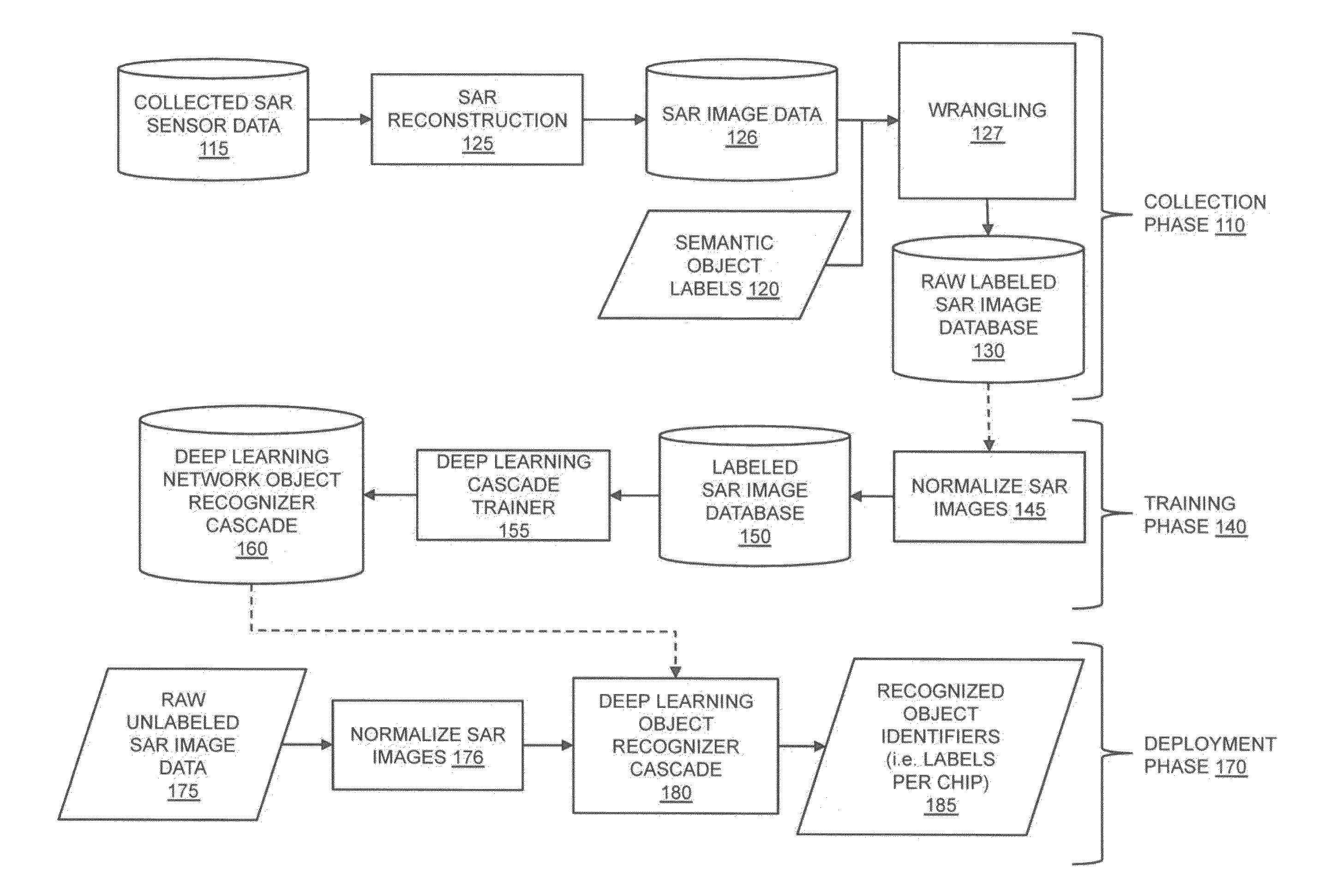
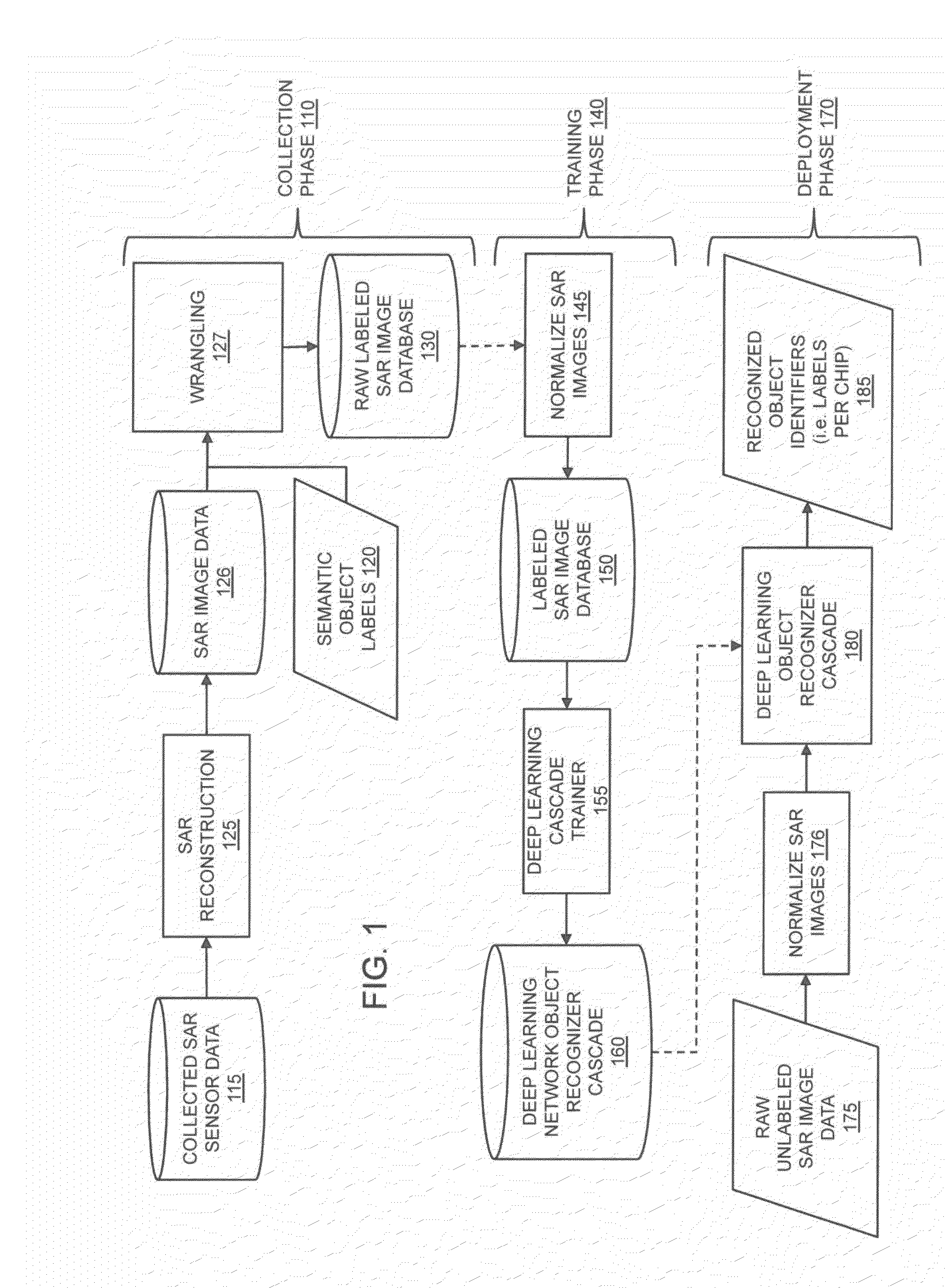
[0028]FIG. 1 illustrates an exemplary embodiment of a system-level process for collecting SAR imagery, training a deep learning network, and deploying a trained deep learning network to recognize objects within SAR (synthetic aperture radar) images, in accordance with the present disclosure. The process comprises three phases: a Collection Phase 110, a Training Phase 140, and a Deployment Phase 170.

[0029]In Collect Phase 110, embodiments of the present invention can receive Collected SAR Sensor Data 115 and Semantic Object Labels 120, and based on those inputs, produce a Raw Labeled SAR Image Database 130 suitable for training an object reco...


PUM


Abstract

The present invention is directed to systems and methods for detecting objects in a radar image stream. Embodiments of the invention can receive a data stream from radar sensors and use a deep neural network to convert the received data stream into a set of semantic labels, where each semantic label corresponds to an object in the radar data stream that the deep neural network has identified. Processing units running the deep neural network may be collocated onboard an airborne vehicle along with the radar sensor(s). The processing units can be configured with powerful, high-speed graphics processing units or field-programmable gate arrays that are low in size, weight, and power requirements. Embodiments of the invention are also directed to providing innovative advances to object recognition training systems that utilize a detector and an object recognition cascade to analyze radar image streams in real time. The object recognition cascade can comprise at least one recognizer that receives a non-background stream of image patches from a detector and automatically assigns one or more semantic labels to each non-background image patch. In some embodiments, a separate recognizer for the background analysis of patches may also be incorporated. There may be multiple detectors and multiple recognizers, depending on the design of the cascade. Embodiments of the invention also include novel methods to tailor deep neural network algorithms to successfully process radar imagery, utilizing techniques such as normalization, sampling, data augmentation, foveation, cascade architectures, and label harmonization.

Description

CROSS-REFERENCE TO RELATED APPLICATIONS[0001]This application claims priority under 35 U.S.C. §119(e) to U.S. Provisional Patent Application No. 62 / 025,075, entitled “A Method for Fast and Accurate Recognition of Objects in Radar Imagery,” filed Jul. 16, 2014.FIELD OF THE INVENTION[0002]Embodiments of the present invention relate to systems and methods for improving the automated recognition of objects from flying vehicles using radar imagery and related onboard image processing techniques. More particularly, embodiments of the present invention relate to systems and methods for utilizing deep learning algorithms, onboard pipelined processing architectures, and improvements in portable computing systems to improve automated onboard recognition of objects within synthetic aperture radar signals obtained from flying vehicles.BACKGROUND[0003]The general problem of computerized object detection in images has been studied for decades, and many techniques are known in the art. Although th...

Claims


Application Information

Patent Timeline
Patent Type & Authority Applications(United States)
IPC IPC(8): G06N3/08G01S13/90G06N3/04
CPCG06N3/08G06N3/04G01S13/9035G01S7/417G01S13/90G01S13/904G01S13/9029G06N3/045G06N3/0463G01S13/9027
Inventor KAUFHOLD, JOHN, PATRICK
Owner GENERAL DYNAMICS MISSION SYST INC
Why Eureka
Try Eureka