Method for measuring a high accuracy height map of a test surface

a high-accuracy, height-mapped technology, applied in the direction of instruments, measurement devices, drawing from basic elements, etc., can solve the problem of taking a long time to measure the total test surfa

Active Publication Date: 2016-01-28
MITUTOYO CORP
View PDF4 Cites 17 Cited by
  • Summary
  • Abstract
  • Description
  • Claims
  • Application Information

AI Technical Summary

Benefits of technology

[0006]There has arisen a need for an improved method for measuring a high accuracy height map of a test surface using an optical profil...

Problems solved by technology

If for each height map the operator has to automatically or manually find the position in which the test surface is with...

Method used


Image

  • Method for measuring a high accuracy height map of a test surface
  • Method for measuring a high accuracy height map of a test surface
  • Method for measuring a high accuracy height map of a test surface

Examples


Embodiment Construction

[0062]The particulars shown herein are by way of example and for purposes of illustrative discussion of the embodiments of the present invention only and are presented in the cause of providing what is believed to be the most useful and readily understood description of the principles and conceptual aspects of the present invention. In this regard, no attempt is made to show structural details of the present invention in more detail than is necessary for the fundamental understanding of the present invention, the description taken with the drawings making apparent to those skilled in the art how the forms of the present invention may be embodied in practice.

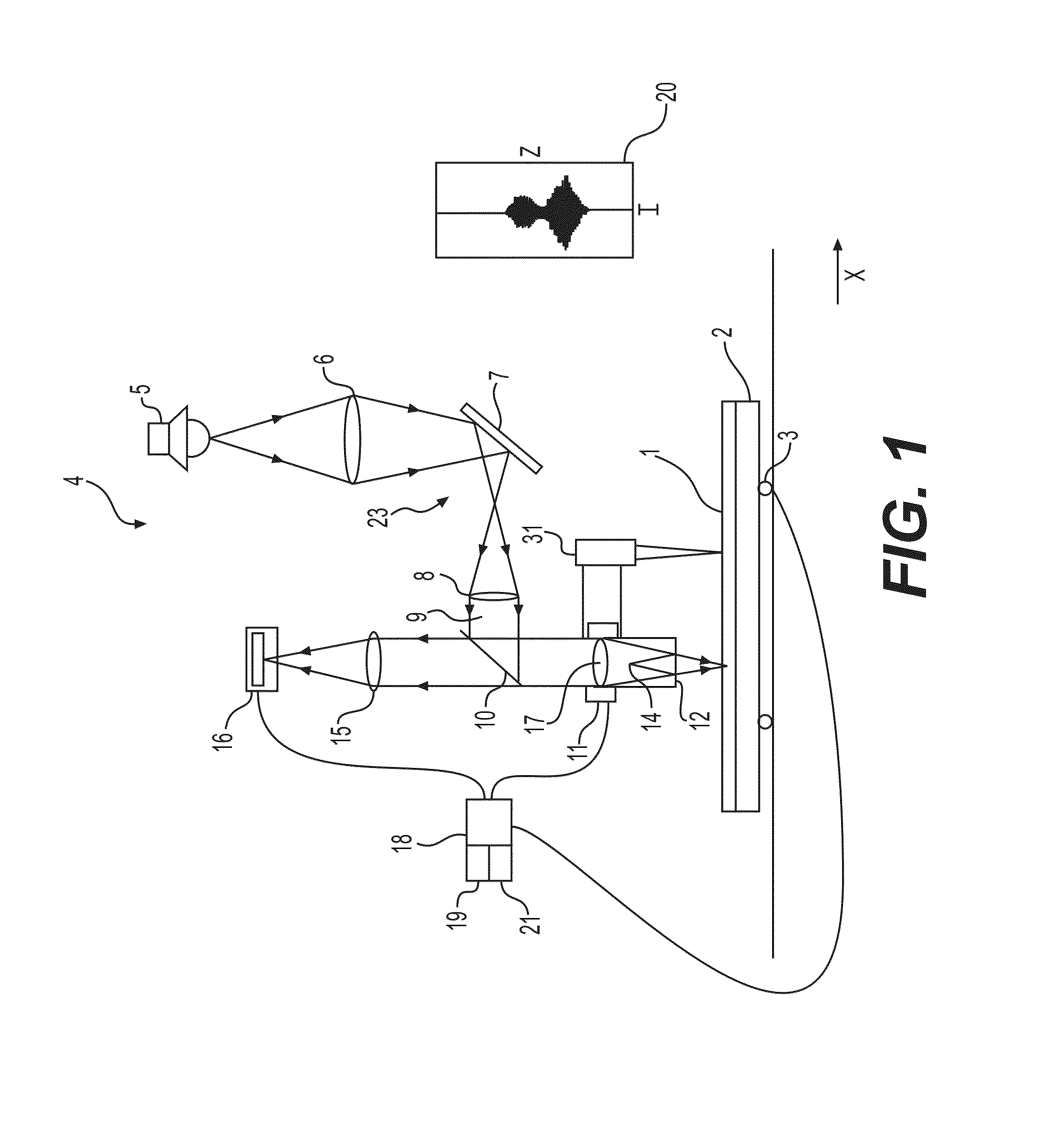
[0063]Referring to the drawings wherein like characters represent like elements, FIG. 1 depicts an interferometer apparatus 4 for determining a property of a sample according to a feature. The interferometer apparatus as depicted is a Mirau interferometer. Alternatively Michelson and / or Linnik interferometer apparatus may be used...


PUM


Abstract

Method for measuring a height map of a test, including measuring a coarse height map of the test surface with a pre-map sensor provided to an optical profiler with a relatively long working distance and/or a large field of view, storing the coarse height map in a memory, subdividing the coarse height map into sections appropriate for the field of view of a high resolution optical profiler sensor provided to the optical profiler, calculating corresponding X, Y and Z positions for the optical profiler sensor with respect to the test surface, calculating a trajectory in the X, Y, Z-direction for the optical profiler sensor with respect to the test surface using the calculated X, Y, Z-positions, moving the optical profiler in the X, Y, Z-direction with respect to the test surface according to the trajectory, and measuring a high accuracy height map with the high resolution optical profiler sensor.

Description

CROSS-REFERENCE TO RELATED APPLICATIONS[0001]The present application claims priority under 35 U.S.C. §119 of European Application No. 14178509.7, filed on Jul. 25, 2014, the disclosure of which is expressly incorporated by reference herein in its entirety.BACKGROUND OF THE INVENTION[0002]1. Field of the Invention[0003]The invention relates to a method for measuring a high accuracy height map of a test surface using a multi sensor optical profiler.[0004]2. Description of Related Art[0005]Typically for 3D optical profiling systems is that the height map accuracy has an inverse relation to the vertical scan range and vertical scanning speed. A high accuracy optical profiler sensor may have a limited field of view, for example the field of view may be 0.1*0.1 mm while the test surface may be much larger. Therefore there is a need to move the test surface underneath the sensor from a first section of the test surface to a subsequent section of the test surface so that multiple height map...

Claims


Application Information

Patent Timeline
IPC IPC(8): G06T11/20G01B11/00G01B11/22
CPCG06T11/206G01B11/002G01B11/22G01B11/2441G01B11/245G01B2210/52
Inventor ZUIDERWEG, ADRIAAN TIEMENQUAEDACKERS, JOHANNES ANNAVISSCHER, HARM
Owner MITUTOYO CORP
Why Eureka
Try Eureka