Lamp Holder

Active Publication Date: 2016-01-28
DONGGUAN JINZHUN ELECTRICAL
View PDF0 Cites 3 Cited by
  • Summary
  • Abstract
  • Description
  • Claims
  • Application Information

AI Technical Summary

Benefits of technology

The present invention provides a lamp holder that can be easily installed on a decorative shelter. The rotary handle can be turned without any limitation after it is installed. The lamp holder also looks better after installation.

Problems solved by technology

If the knob 142 is installed at the rear of the shelter (such as a decorative plate), the knob 142 will be attached closely to the shelter, and the operation of turning the knob 142 becomes very inconvenient.
If the knob 142 is installed at the front of the shelter (such as a decorative plate), the aesthetic look of the lamp holder is affected adversely in addition to the inconvenient operation of the knob 142.

Method used


Image

  • Lamp Holder
  • Lamp Holder
  • Lamp Holder

Examples


Embodiment Construction

[0028]The technical characteristics, contents, advantages and effects of the present invention will be apparent with the detailed description of a preferred embodiment accompanied with related drawings as follows.

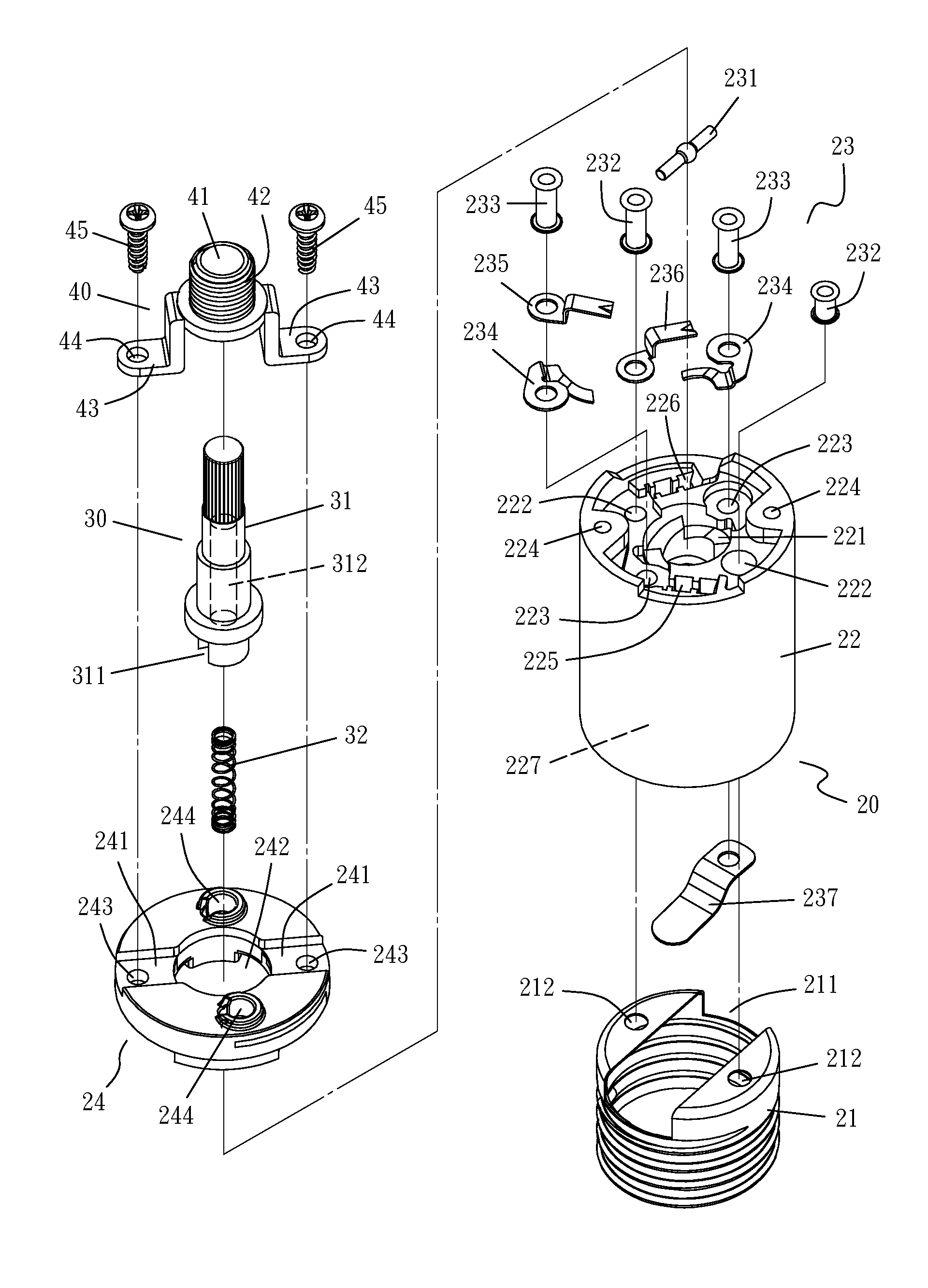
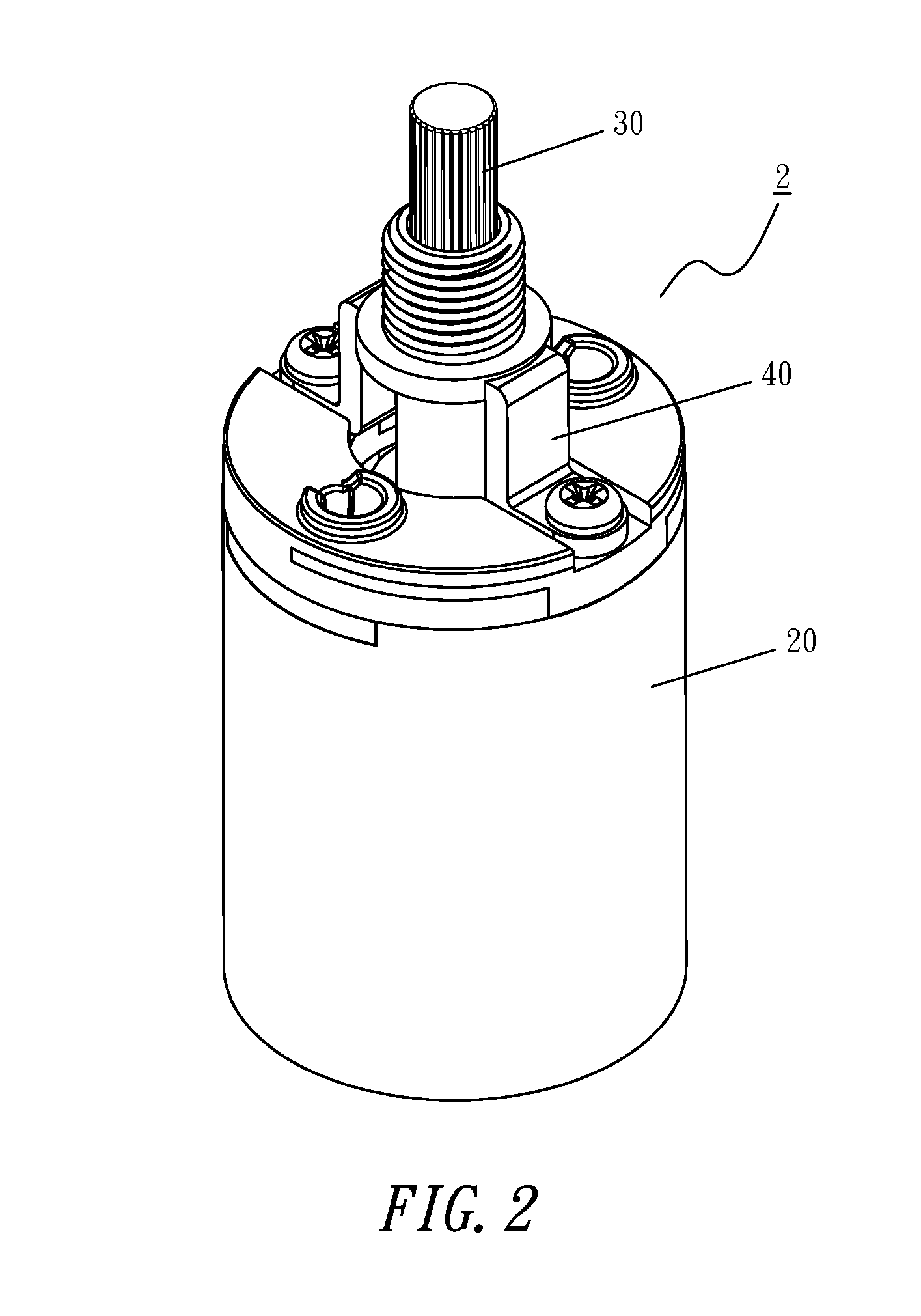
[0029]With reference to FIG. 2 for a lamp holder 2 of the first preferred embodiment of the present invention, the lamp holder 2 comprises a main body 20, a switch device 30 and a mounting bracket 40, wherein the main body 20 is a cylindrical body, and the switch device 30 is installed at an end of the main body 20, and the mounting bracket 40 encloses the switch device 30 and connects the main body 20.

[0030]With reference to FIGS. 3 to 8, the main body 20 is comprised of a cylindrical casing 21, an insulated casing 22, an electrically conductive module 23 and an insulated top cover 24, wherein the cylindrical casing 21 is made of a conducting plate and manufactured into the shape of an open barrel, and a screw thread is formed on an inner wall of the cylindrical casing 21 ...


PUM


Abstract

A lamp holder includes a main body, a switch device and a mounting bracket. The main body has an axial end for connecting a light emitting element and another axial end having an electrically conductive module, and the switch device is installed in the main body, and the switch device and the electrically conductive module jointly control the light emitting element to be turned on or off. The rotary handle of the switch device is installed at an axial end of the main body and protruded out from the main body, and the mounting bracket encloses the rotary handle and locks with the main body. Therefore, the lamp holder can be installed onto a decorative shelter conveniently, and the rotary handle can be turned without limitation, and the lamp holder has a good appearance.

Description

BACKGROUND OF THE INVENTION[0001]1. Field of the Invention[0002]The present invention relates to a lamp holder, and more particularly to the lamp holder having a conveniently installed decorative shelter, and a rotary handle rotatable without limitation and providing a better aesthetic look.[0003]2. Description of the Related Art[0004]With reference to FIG. 1 for a conventional lamp holder 1, the lamp holder comprises a cylindrical casing 11, an insulated casing 12, an insulated holder body 13 and a switch device 14. The cylindrical casing 11 is electrically conductive and provided for screwing and connecting a light emitting element (such as a light bulb, not shown in the figure), and a first electrode of the light emitting element is coupled to a positive electrode of a power supply (such as utility power) installed in the insulated holder body 13 to achieve an electric connection for a close or open circuit, and a second electrode of the light emitting element is in contact with ...

Claims


Application Information

Patent Timeline
IPC IPC(8): H01R13/70H01H3/08H01H3/34H01R33/22
CPCH01R13/70H01H3/34H01H3/08H01R33/22
Inventor PENG, TE-SHUI
Owner DONGGUAN JINZHUN ELECTRICAL
Why Eureka
Try Eureka