Garment separator

a technology of garment separator and garment rod, which is applied in the direction of snap fasteners, buckles, mechanical devices, etc., can solve the problems of insufficient, cumbersome, inconvenient, etc., and the ability of known garment separators to attach and detach from clothing rods,

Inactive Publication Date: 2016-02-04
SAC CONCEPTS
View PDF12 Cites 9 Cited by
  • Summary
  • Abstract
  • Description
  • Claims
  • Application Information

AI Technical Summary

Benefits of technology

[0007]The invention provides a garment separator that overcomes the hereinafore-mentioned disadvantages of the heretofore-known devices and methods of this general type and that provides consistent spacing between garments hanging from clothing hangers.

Problems solved by technology

Although there are numerous types of clothing hangers and clothing rods, which together allow users to store garments in home closets or on racks in a retail environment, little attention has been paid to effective solutions to keep garments separated from each other.
A number of known devices which attempt to provide spacing between garments are, for various reasons, inadequate, inefficient, or cumbersome.
For example, some known garment separators are difficult to attach and detach from a clothing rod.
These devices feature members that lock together, but require special tools or great force to remove.
Once closed, the snap enclosures are hidden inside the hemi-shells and access to them is restricted.
Other existing garment separators are not adaptable to different sizes, i.e., outer diameters, and shapes, e.g., square, round, ovular, etc., of clothing rods.
Yet other garment separators slide easily on the clothing rod, but are thus too easily displaced from their desired position, allowing garments to bunch together.
One of the problems with utilizing a sleeve is that the sleeve is semi-permanent and in order to move or remove the sleeve or create areas along the bar that are free from the organizer, a user must first remove multiple garments that are hanging from the sleeve, which is a burdensome and time-consuming task.
In addition, the sign attached to the clamping end makes it difficult to operate the clamp.
The protruding sign further creates an aesthetically unpleasant clamp unacceptable for home use.

Method used


Image

  • Garment separator
  • Garment separator
  • Garment separator

Examples


Embodiment Construction

[0041]While the specification concludes with claims defining the features of the invention that are regarded as novel, it is believed that the invention will be better understood from a consideration of the following description in conjunction with the drawing figures, in which like reference numerals are carried forward. It is to be understood that the disclosed embodiments are merely exemplary of the invention, which can be embodied in various forms.

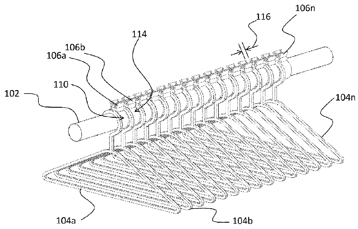
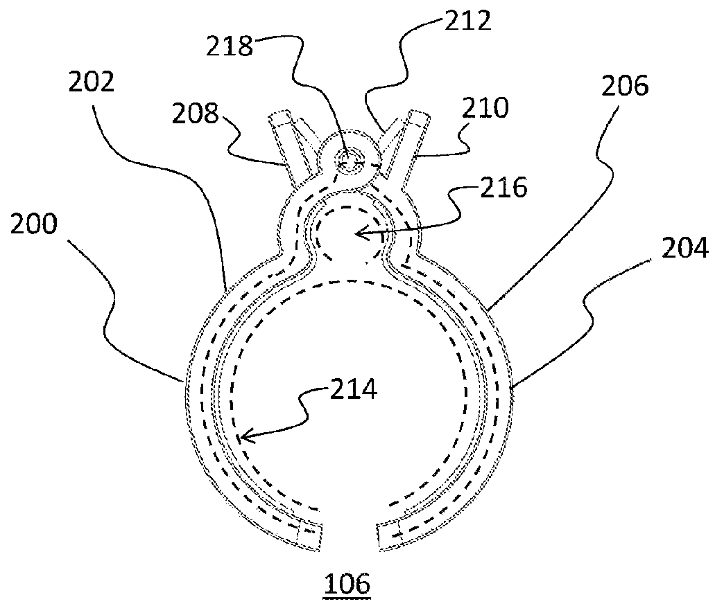
[0042]The present invention provides a novel and efficient garment separator, garment separator assembly, and method designed to maintain even spacing between individual hangers hanging from a clothing rod. Embodiments of the invention provide the user with the ability to utilize the garment separator assembly with a variety of clothing rods having different diameters. In addition, embodiments of the invention provide a separator forming a single unit that can quickly and easily be attached and detached from the clothing rod.

[0043]Refe...


PUM


Abstract

A garment separator assembly is provided including at least two separators. Each separator includes a first member defining a first half of the separator; and a second member defining an opposing second half of the separator. The second member is coupled to the first member and, together with the first member, defines a first inner-surface circumference and a second inner-surface circumference adjacent and non-coaxial with the first inner-surface circumference. The first inner-surface circumference is larger than the second inner-surface circumference. The first inner-surface circumference is shaped and sized to mate with a first outer diameter of a standard clothing rod; and the second inner-surface circumference is shaped and sized to mate with a second outer diameter of a clothing rod, wherein the second outer diameter is smaller than the first outer diameter of the standard clothing rod.

Description

CROSS-REFERENCE TO RELATED APPLICATION[0001]This application is a continuation-in-part and claims priority to U.S. application Ser. No. 14 / 445,507, filed on Aug. 8, 2014, the entirety of which is incorporated herein by reference.FIELD OF THE INVENTION[0002]The present invention relates generally to a garment separator, and, more particularly, relates to a garment separator for maintaining even spacing between garments.BACKGROUND OF THE INVENTION[0003]Many types of garments, i.e., clothing, are commonly stored on clothing hangers. Although there are numerous types of clothing hangers and clothing rods, which together allow users to store garments in home closets or on racks in a retail environment, little attention has been paid to effective solutions to keep garments separated from each other. In particular, little effort has been spent developing a way to easily maintain consistent spacing between garments. Such uniformity is not only aesthetically pleasing, it also allows garments...

Claims


Application Information

Patent Timeline
Patent Type & Authority Applications(United States)
IPC IPC(8): A47G25/14A47B61/00F16B1/00F16B2/00F16B2/10
CPCA47G25/1471F16B1/00F16B2001/0035A47B61/003F16B2/10F16B2/005F16B2200/83
Inventor PERRIN, STACY, ELIZABETH
Owner SAC CONCEPTS
Why Eureka
Try Eureka