Concrete curb form spacer

a form spacer and concrete technology, applied in the field of concrete form spreaders, can solve the problems of cumbersome process, difficult to maintain uniform spacing between forms, and difficulty in maintaining such consistency in forms

Inactive Publication Date: 2004-06-22
GONZALES REYES
View PDF9 Cites 8 Cited by
  • Summary
  • Abstract
  • Description
  • Claims
  • Application Information

AI Technical Summary

Benefits of technology

The spacing and leveling of linear forms is accomplished by using the spacer / leveler apparatus of the present invention as the forms are installed, and / or by adjusting the positions of the forms using the spacer / leveler apparatus following installation but prior to pouring concrete. A single spacer / leveler unit may be used to set or adjust a given set of parallel forms by traveling from one end of the linear forms to the other, making adjustments along the way. The notches at either end of the spacer fit flush against the top inside corners of the linear forms helping to establish uniform positioning and preventing the spacer from falling or becoming dislodged during adjustments to the forms. Alternatively, additional spacers, or spacer / levelers may be employed along sections of the parallel linear forms, particularly with forms covering long distances.
It is therefore a primary object of the present invention to provide an efficient and reliable method and apparatus for use in establishing a consistent distance between linear forms for concrete structures.
It is also an important object of the present invention to provide an apparatus for use in setting level linear forms for concrete structures with consistent spacing that is not easily dislodged during installation or adjustments of the forms.
It is another object of the invention to reduce the time and labor used to properly set parallel forms for concrete structures.

Problems solved by technology

It is often difficult to maintain such consistency in the forms, especially over long distances.
It is even more difficult with wider curbs such as mow strips.
Unfortunately, as the installation progresses, such make-shift spacers tend to drop, fall or otherwise become dislodged making it a cumbersome process to maintain uniform spacing between forms, particularly with the angled toeboards used for curbs.
This is a labor intensive and inefficient process.

Method used


Image

  • Concrete curb form spacer
  • Concrete curb form spacer
  • Concrete curb form spacer

Examples


Embodiment Construction

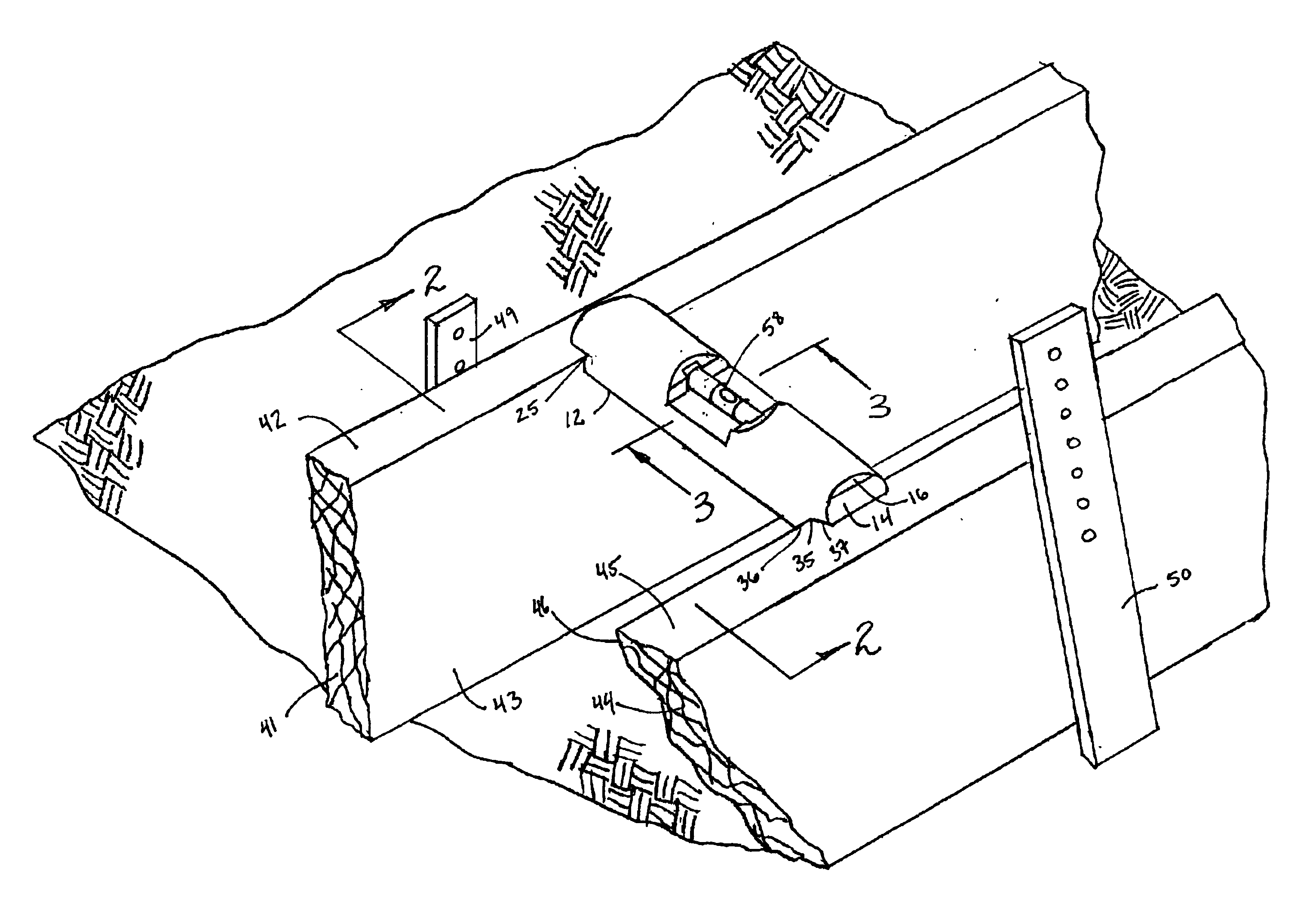
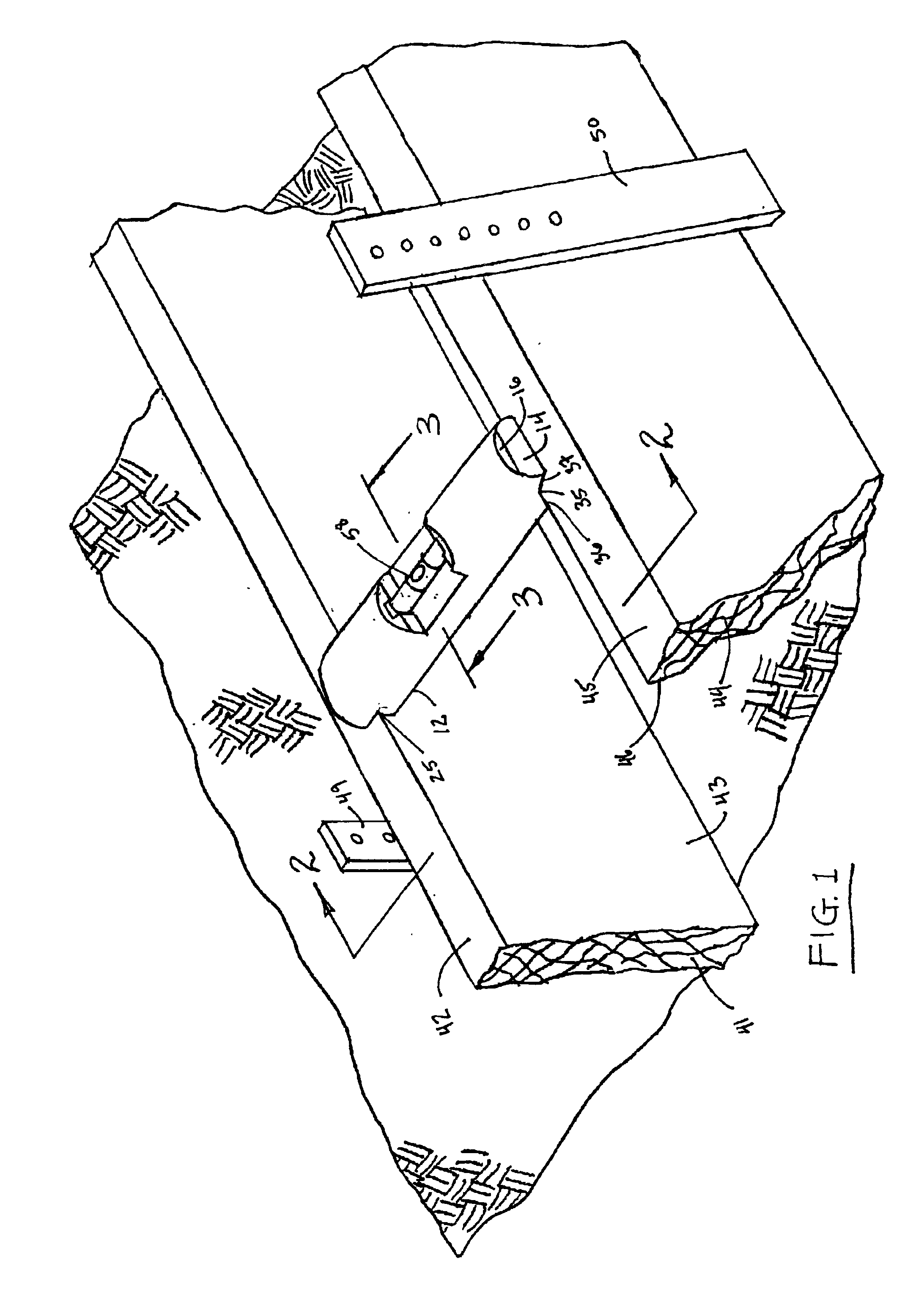
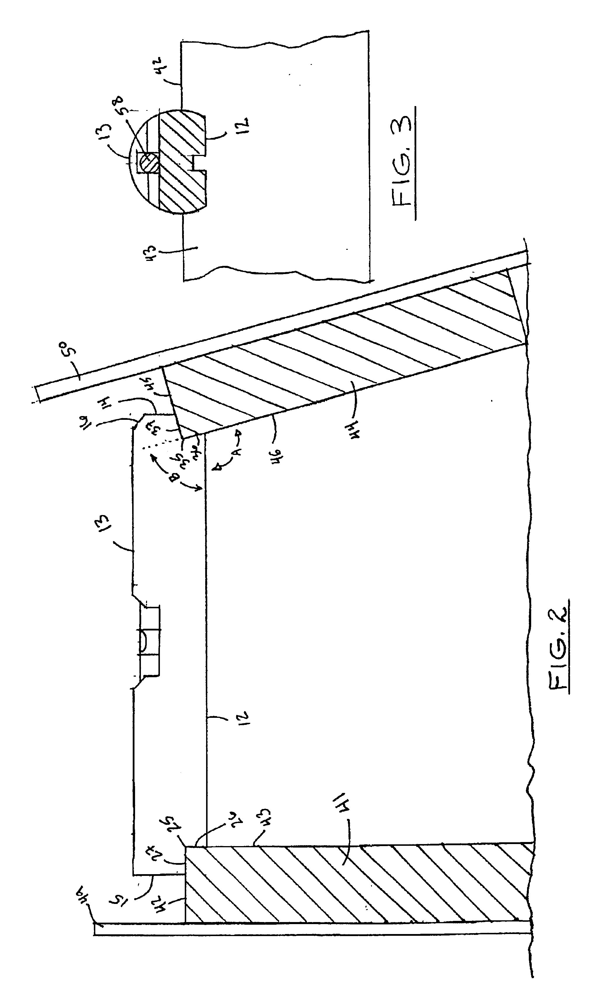
Referring to the drawings wherein like reference characters designate like or corresponding parts throughout the several views, and referring particularly to FIGS. 1-4 it is seen that the invention includes an elongated body member 11 having a flat bottom 12, a rounded top 13, a proximal end 14 and a distal end 15. Body member 11 is designed to bridge the gap between a pair of parallel linear form boards 41 and 44. Form board 41 illustrated in FIGS. 1 and 2 is in the form of a vertical backboard supported by stake 49, and form board 44 is in the form of an angled toeboard supported by angled stake 50 for establishing the face of a curb. In an alternative environment illustrated in FIG. 7, both boards 41 and 44 (and stakes 49, 50) are vertical.

Returning to FIGS. 1-4, a first orthogonal notch 25 is provided on the distal end 15 of body member 11 at the corner where bottom 12 meets end 15. Notch 25 includes a first surface 26 that is perpendicular to flat bottom 12, and a horizontal su...


PUM

PropertyMeasurementUnit
distanceaaaaaaaaaa
angleaaaaaaaaaa
angleaaaaaaaaaa

Abstract

A method and apparatus for establishing and maintaining consistent spacing between parallel forms for concrete structures. The elongated spacer includes notches at either end for flush engagement with the upper corners of the parallel forms. An angled notch may be provided for engagement with angled toeboards used in curb construction, and a level may be included for use in setting the parallel forms at a consistent level.

Description

1. Field of the InventionThe present invention relates to forming concrete, and more particularly to a unique form spreader for use in setting forms for concrete curbs, mow strips and the like.2. Description of the Prior ArtConcrete curbs are formed using a pair of elongated panels or boards that must be set in position in parallel before the concrete slurry is poured between them. The parallel positioning requires that the panels or boards be separated by a consistent spacing, and that the tops of both panels or boards be at the same level. It is often difficult to maintain such consistency in the forms, especially over long distances. It is even more difficult with wider curbs such as mow strips.The most common method for setting forms for concrete curbs is to excavate the area where the curb is to be installed, and then install two sets of linear boards in the area. The boards are placed end-to-end and turned on their sides to form a pair of parallel lines. The boards are held in...

Claims


Application Information

Patent Timeline
Patent Type & Authority Patents(United States)
IPC IPC(8): E01C19/00E01C19/50
CPCE01C19/506Y10T428/24777
Inventor GONZALES, REYES
Owner GONZALES REYES
Why Eureka
Try Eureka