Eccentric Drive

a drive and eccentric technology, applied in the field of eccentric drive drives, can solve the problems of loss of the flywheel body, increased maintenance effort, high repair cost and maintenance effort, etc., and achieve the effect of increasing surface area, reducing maintenance costs, and increasing frictional forces

Inactive Publication Date: 2016-02-04
DEERE & CO
View PDF11 Cites 0 Cited by
  • Summary
  • Abstract
  • Description
  • Claims
  • Application Information

AI Technical Summary

Benefits of technology

[0007]According to the invention, an eccentric drive of the type mentioned above is constructed in such a manner that the flywheel body can be connected to the third shaft via a conically tapering bushing arranged rotatably fixedly and axially fixably on the third shaft, wherein the flywheel body has a conically tapering hub corresponding to the outer surface of the bushing, with which hub the flywheel body can be pressed on the outer surface of the bushing by means of a shaft nut arranged on the third shaft. Owing to this arrangement, particularly the conical formation of the bushing and the flywheel body, a much larger surface area is created on which a clamping torque can be exerted, whereby greater frictional forces can act at the connection of flywheel body and bushing, with equal or even less clamping torque. The use of a conical bushing also makes it possible to adapt already existing flywheel bodies by slight modifications, so that the eccentric drives assembled according to the conventional method can be modified or converted at low expense.
[0008]A recess for receiving a rotational driver is formed on the outer surface of the bushing and a broached groove is formed on the inner side of the hub. This measure proves to be easy to assemble and inexpensive, and therefore also offers the above-mentioned advantages.

Problems solved by technology

If there is too little clamping torque or during highly stressed operating states, the shaft nut can come loose on the shaft, threatening the loss of the flywheel body, with which irreparable damage to the eccentric drive and its environment and therefore also high repair costs and maintenance effort can arise.
In order to counteract this, it was attempted to form the shaft nut and the driveshaft larger for the purpose of being able to apply a larger clamping torque, but this entails material and tool costs as well as increased maintenance effort.
Another solution was to lock the flywheel body and the shaft together by a transverse pin, whereby the production and assembly expense became uneconomical.

Method used


Image

  • Eccentric Drive
  • Eccentric Drive
  • Eccentric Drive

Examples


Embodiment Construction

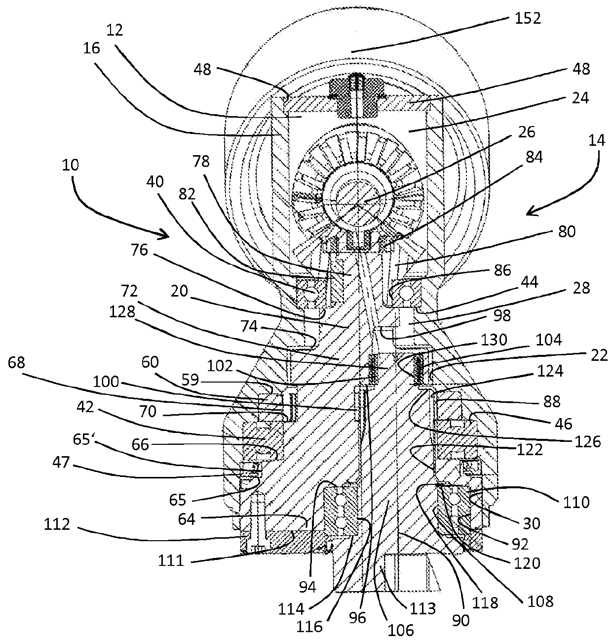
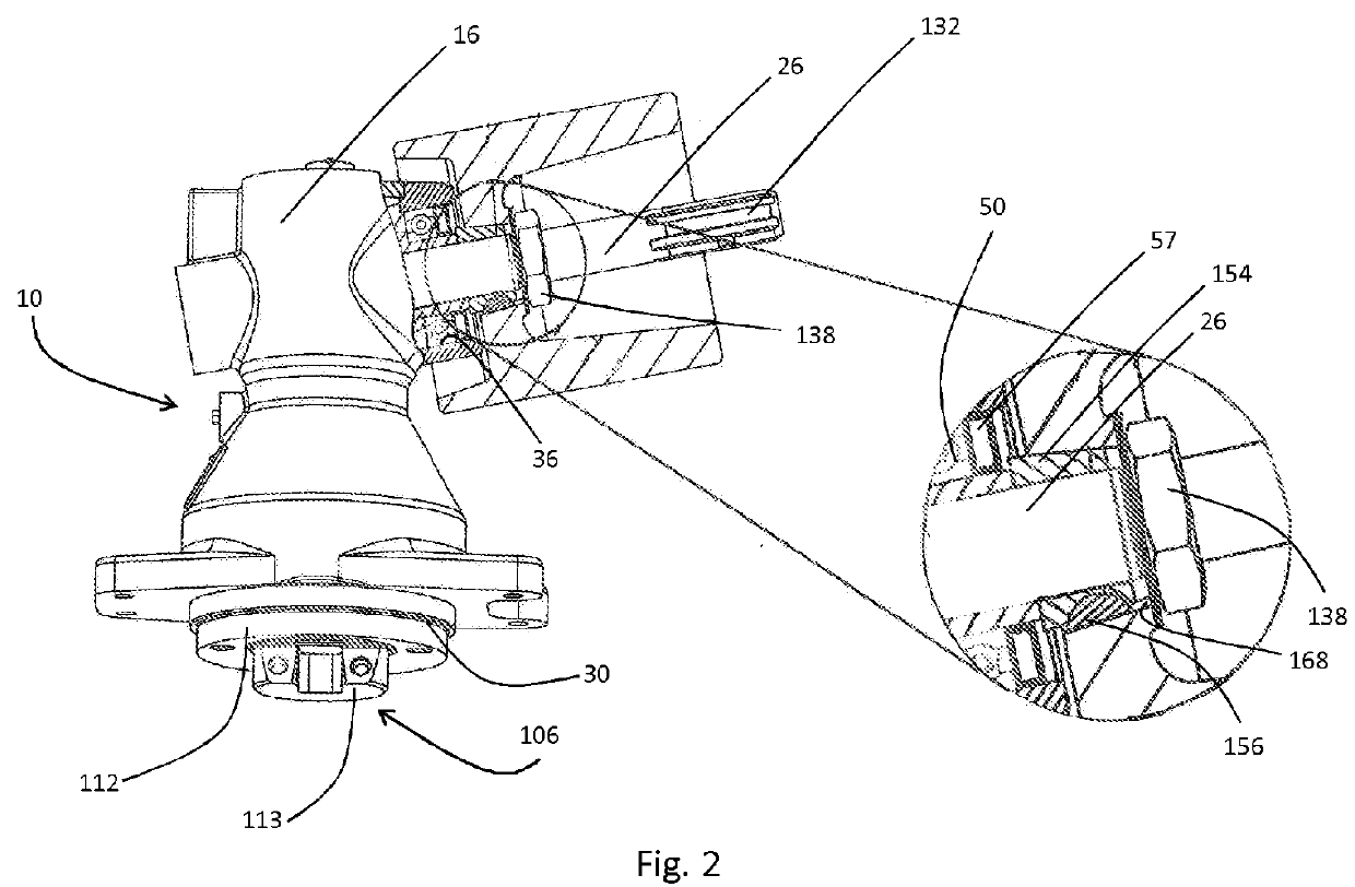
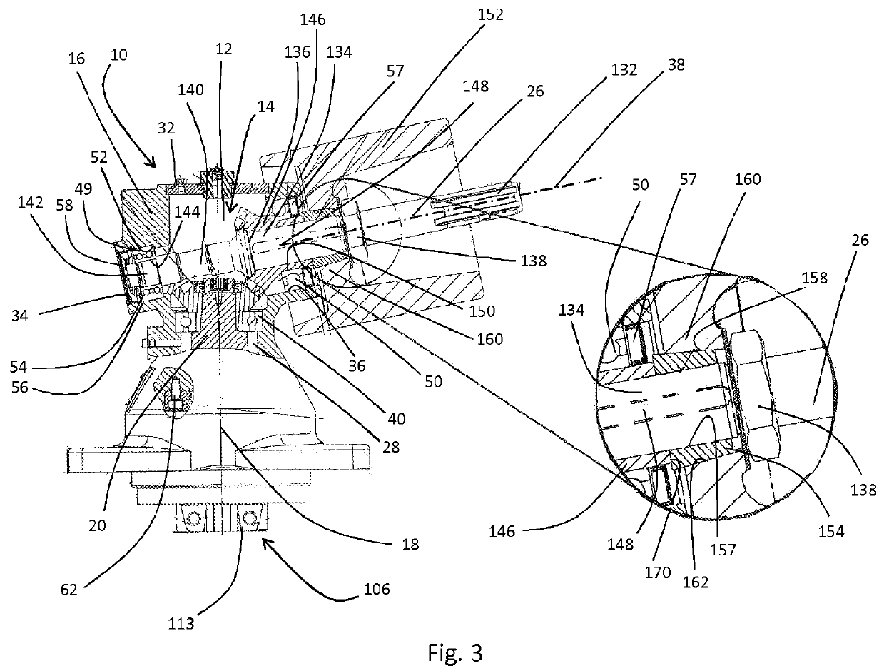
[0017]FIGS. 1-3 show an eccentric drive 10 having a gearbox housing 16 surrounding a gearbox chamber 12 of a right-angle gear unit 14. The gearbox housing 16 extends substantially along the axis of rotation 18 of a first shaft 20, the axis of rotation 18 defining a longitudinal direction of the eccentric drive 10. The gearbox chamber 12 is subdivided into a first gearbox chamber 22, which substantially surrounds the first shaft 20, and a second gearbox chamber 24, which substantially surrounds a third shaft 26 arranged at an angle (nearly a right angle) to the longitudinal direction. The gearbox chamber regions 22, 24 are formed adjoining one another in the longitudinal direction and have a common cylindrical transition region 28, which is arranged approximately centrally in relation to the longitudinal extent of the gearbox housing 16 and coaxially with the axis of rotation 18, and by which a connection of the gearbox chamber regions 22, 24 is defined.

[0018]In the first gearbox cha...


PUM


Abstract

An eccentric drive for driving cutter mechanisms on mowing attachments for combine harvesters is provided that comprises a gearbox housing (16), a gearbox chamber (12) enclosed by the gearbox housing (16), a first shaft (20) mounted in the gearbox housing (16), a cavity (88) formed in the first shaft (20) and having its cross-sectional center of gravity eccentric to the axis of rotation (18), in which cavity a second shaft (106) is rotatably mounted, having a toothed region (124), which is engaged with the gearbox housing (16), and a shaft end region (113) protruding axially from the cavity (88) of the first shaft (20), and a third shaft (26) wherein a flywheel body (152) can be connected to the third shaft (26) via a bushing (154) that is tapered on its outer surface (158) and is arranged rotatably fixedly and axially fixably on the third shaft (26).

Description

FIELD OF THE INVENTION[0001]The invention relates to drives for eccentric drives.BACKGROUND OF THE INVENTION[0002]Eccentric drives that have gear transmissions arranged at an angle to one another and gear shafts arranged one inside another are known in the prior art. Eccentric drives with gear shafts arranged one inside another provide a compact design and are one possibility for realizing eccentric drives. Eccentric drives are used, for example, in agriculture for driving cutter mechanisms on mowing attachments for combine harvesters. Such eccentric drives can additionally have a flywheel body on their driveshaft, which is mounted on the shaft and rotatably fixed thereon. It is common to secure this flywheel body rotatably fixedly on the driveshaft by means of a conventional feather key / groove connection and to clamp it via a shaft nut against a shaft shoulder on the driveshaft.[0003]If there is too little clamping torque or during highly stressed operating states, the shaft nut ca...

Claims


Application Information

Patent Timeline
Patent Type & Authority Applications(United States)
IPC IPC(8): F16H1/20A01D41/12F16H29/12
CPCF16H1/203A01D41/12F16H29/12A01D34/30A01D41/142F16D1/096
Inventor GIL, MONICA
Owner DEERE & CO
Why Eureka
Try Eureka