Electric pump

Inactive Publication Date: 2016-02-18
AISAN IND CO LTD
View PDF0 Cites 5 Cited by
  • Summary
  • Abstract
  • Description
  • Claims
  • Application Information

AI Technical Summary

Benefits of technology

The patent describes a technology to prevent foreign objects from entering the space between a rotor and a shaft in an electric pump. This is achieved through the use of a wall and a magnet that causes the fluid (which contains the foreign objects) to rotate and move towards the outer edge of the magnet, away from the space between the rotor and shaft. This prevents the foreign objects from entering the space and potentially causing damage or malfunction.

Problems solved by technology

The entry of foreign bodies into the space between the rotor and the fixed axle hampers the rotation of the rotor.

Method used


Image

  • Electric pump
  • Electric pump
  • Electric pump

Examples


embodiments

First Embodiment

(Configuration of Electric Water Pump 10)

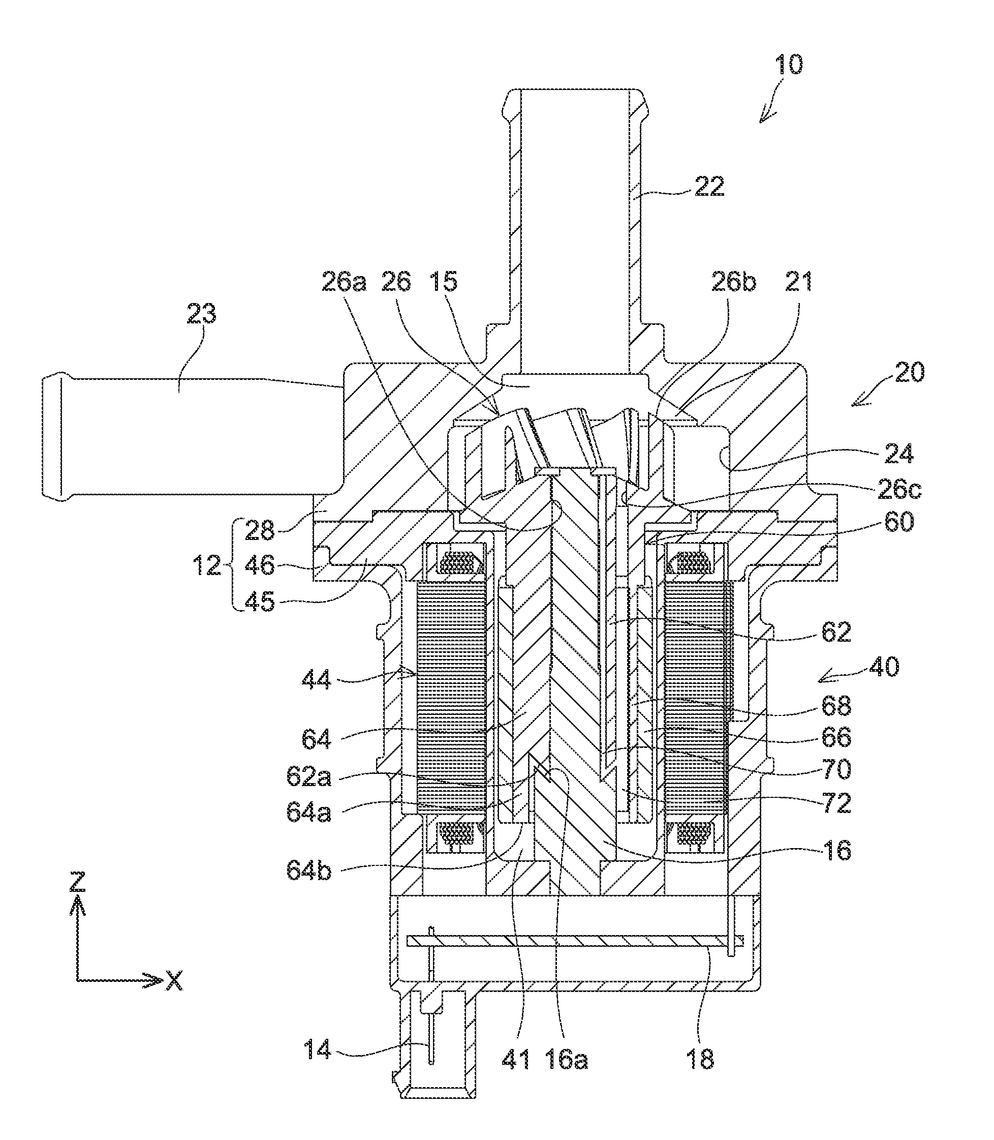
[0033]An electric water pump 10 is for example installed in an engine room of a vehicle, such as an automobile, and used to circulate cooling water that cools an engine, an inverter, and the like. As shown in FIG. 1, the electric water pump 10 comprises a pump portion 20 and a motor portion 40. An outer circumference of the electric water pump 10 is formed by a casing 12. The casing 12 comprises an upper casing 28, a middle casing 45, and a lower casing 46. The casing 12 defines a storage space 15. The storage space 15 comprises a pump chamber 21 and a motor chamber 41.

(Configuration of Pump Portion 20)

[0034]The pump portion 20 is provided in the upper casing 28. In the pump portion 20, an intake opening 22, a discharging opening 23, and the pump chamber 21 are formed by the upper casing 28. Further, the pump portion 20 includes an impeller 26.

[0035]The impeller 26 is housed in the upper casing 28. The impeller 26 has a circul...

second embodiment

Modification of Second Embodiment

[0058]Each of the walls 164 of the second embodiment is curved. The walls alternatively may not be curved. For example, as shown in FIG. 5, the rotor 60 may include uncurved walls 264. Each of the walls 264 may have a lower end face 264a that is similar to the lower end face 164a.

third embodiment

[0059]With reference to FIGS. 6 and 7, aspects of the differences from the first embodiment are described below. In the present embodiment, as shown in FIGS. 6 and 7, the rotor 60 includes walls 364 instead of the walls 64. As shown in FIG. 6, each of the walls 364 projects from the outer circumferential surface of the body 62 toward the tubular portion 68. Each of the walls 364 has a tubular portion 68 side end spaced from the tubular portion 68, and the tubular portion 68 side end does not divide the space between the tubular portion 68 and the body 62. The flow passage 72, present between the tubular portion 68 and the body 62, is not divided by the walls 364 and encircles the body 62. Each of the walls 364 has a lower end face located on a same level as the lower end face 62a of the body 62. The lower end face of each of the walls 364 has a partially cylindrical shape as the lower end face 64a does. As shown in FIG. 7, each of the walls 364 has a semicircular columnar shape.


PUM


Abstract

A rotor of an electric pump may include a body having an inner circumferential surface encircling a shaft; and a magnet located in a motor chamber of a storage space of the pump, and arranged so as to be (i) separated from an outer circumferential surface of the body with an interval in between and (ii) separated from a stator of the pump with an interval in between. The interval between the magnet and the body may communicate the motor chamber and a pump chamber of the storage space. The body may include a groove extending from an end of the inner circumferential surface of the body to the pump chamber. The rotor may further comprise a wall disposed in the interval between the magnet and the outer circumferential surface of the body and at a position being different from the groove in a rotation direction of the rotor.

Description

CROSS-REFERENCE TO RELATED APPLICATION[0001]This application claims priority to Japanese Patent Application No. 2014-166056 filed on Aug. 18, 2014, the contents of which are hereby incorporated by reference into the present application.TECHNICAL FIELD[0002]Teachings disclosed herein relate to an electric pump configured to pressurize and discharge fluid.DESCRIPTION OF RELATED ART[0003]Japanese Patent Application Publication No. 2006-214407 discloses a canned motor pump. The canned motor pump includes a canned motor and a pump portion. The pump portion includes a casing, an intake opening, a discharging opening, a pump chamber, and an impeller. The pump chamber is formed in the casing and houses the impeller. Rotation of the impeller by the canned motor causes fluid to flow into the pump chamber through the intake opening and be discharged out of the pump chamber through the discharging opening. The canned motor includes a rotor configured to rotate the impeller and a fixed axle conf...

Claims


Application Information

Patent Timeline
IPC IPC(8): F04D13/06F04D1/00F04D13/08
CPCF04D13/0606F04D13/08F04D1/00F04D29/588H02K1/2781H02K1/2706H02K1/32
Inventor TORII, HIDEMASA
Owner AISAN IND CO LTD
Why Eureka
Try Eureka