Optical Differential Solar Tracking System

a solar tracking system and differential refraction technology, applied in the field of optical tracking and tracking systems, can solve the problems of preventing more widespread adoption of solar systems, not providing a low-cost, high-precision optical tracking system to track sunlight, and not utilizing differential refraction and dispersion of light to achieve cost-effective and accurate solar tracking systems. , to achieve the effect of reducing maintenance and operation costs

Inactive Publication Date: 2016-02-18
SOLARCITY
View PDF1 Cites 4 Cited by
  • Summary
  • Abstract
  • Description
  • Claims
  • Application Information

AI Technical Summary

Benefits of technology

[0010]In view of the shortcomings of the prior art, it is an object of the present invention to provide low-cost, high-precision solar tracking apparatus and methods that support periodic updates of on-sun orientation with minimal cost of maintenance and operation, without requiring complex computational algorithms of computer or machine vision.

Problems solved by technology

Still, a number of obstacles are preventing more widespread adoption of solar systems.
One of these challenges relates to efficient tracking of the sun as it traverses its daily trajectory in the sky.
A shortcoming of prior art teachings is that they do not provide a low-cost, high-precision optical tracking system to track sunlight.
While refractive devices and differential refractometers have been used for many applications, there has not been a cost-efficient and accurate solar tracking system effectively utilizing differential refraction and dispersion of light.
The prior art teachings while appropriate for some applications, do not provide approaches that are compatible with low-cost, precision-oriented solar tracking systems that are updated on a periodic basis with minimal resources in order to maximize power output generated from their associated solar panel or the entire solar farm.

Method used


Image

  • Optical Differential Solar Tracking System
  • Optical Differential Solar Tracking System
  • Optical Differential Solar Tracking System

Examples


Embodiment Construction

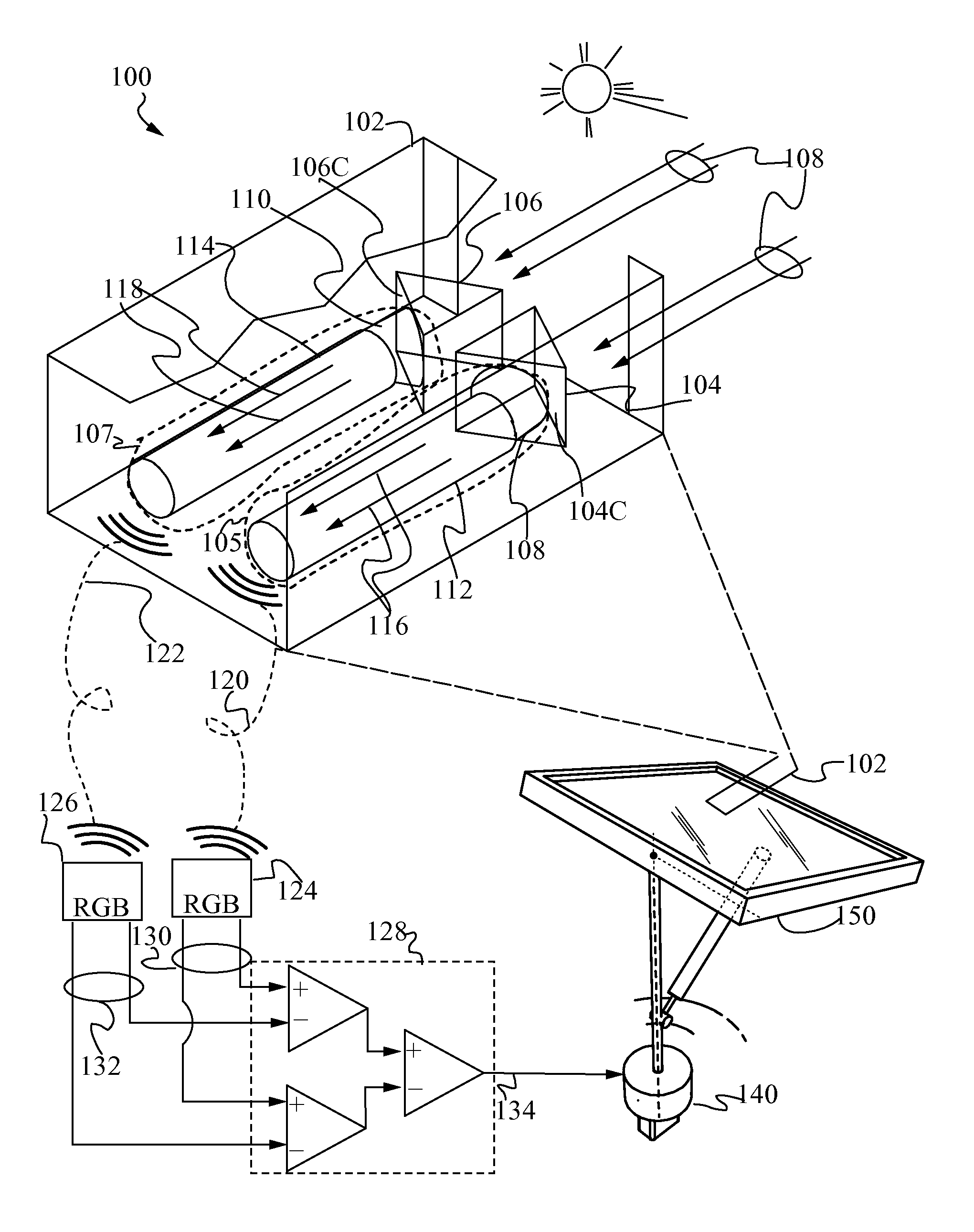
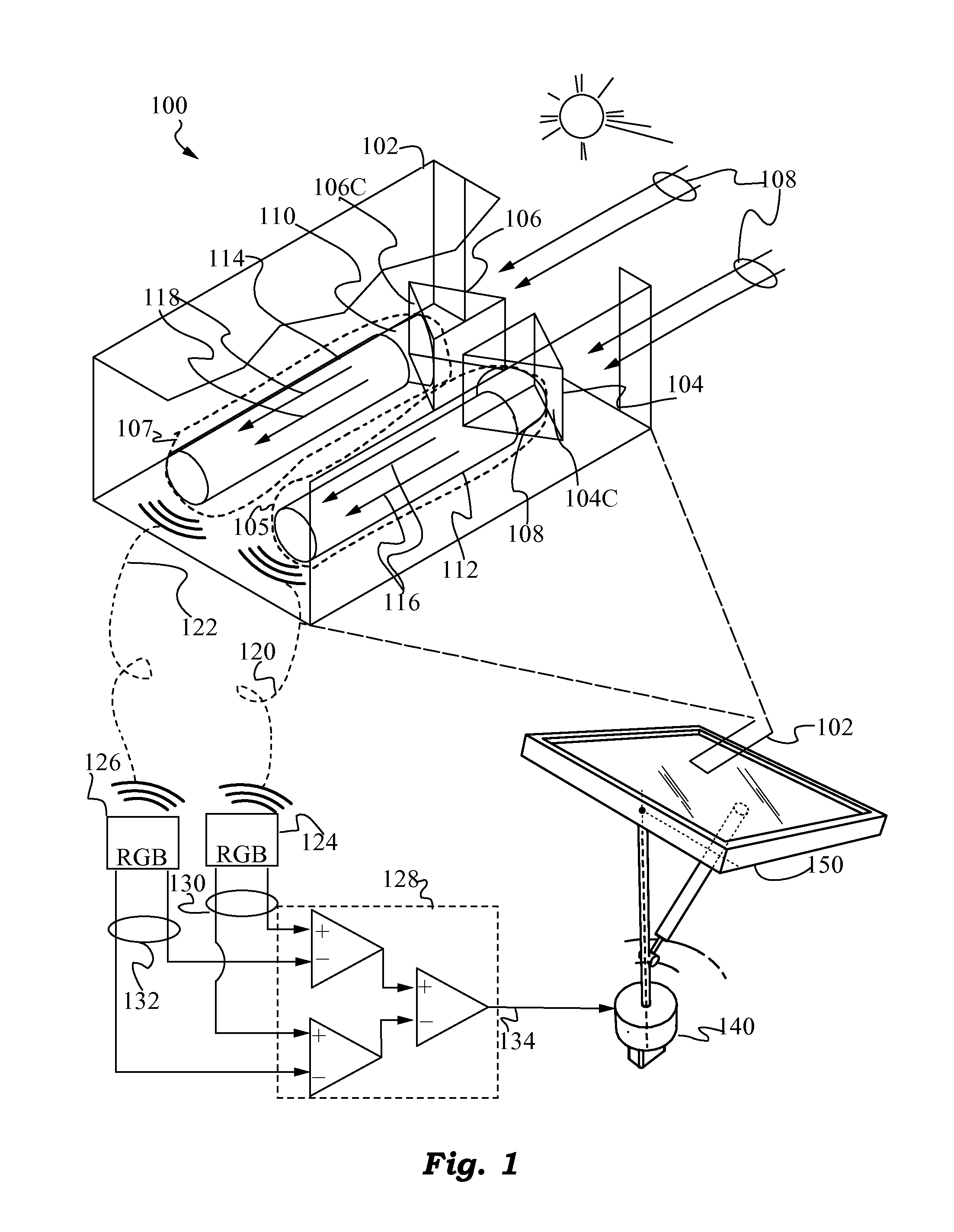
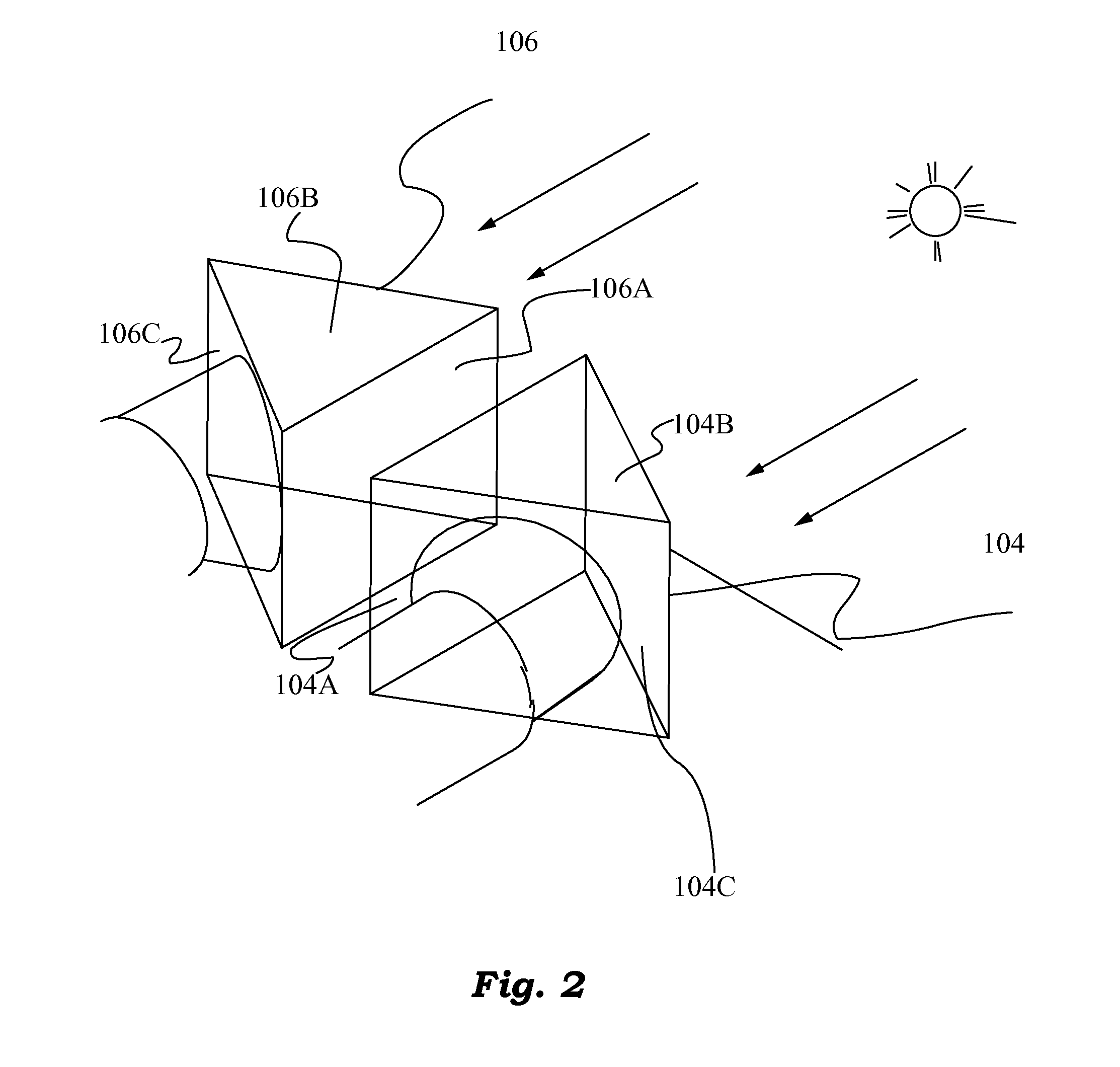
[0037]The figures and the following description relate to preferred embodiments of the present invention by way of illustration only. It should be noted that from the following discussion, alternative embodiments of the structures and methods disclosed herein will be readily recognized as viable alternatives that may be employed without departing from the principles of the claimed invention.

[0038]Reference will now be made in detail to several embodiments of the present invention(s), examples of which are illustrated in the accompanying figures. It is noted that wherever practicable similar or like reference numbers may be used in the figures and may indicate similar or like functionality. The figures depict embodiments of the present invention for purposes of illustration only. One skilled in the art will readily recognize from the following description that alternative embodiments of the structures and methods illustrated herein may be employed without departing from the principle...


PUM


Abstract

A system and method of using differential optical signals to track the orientation of a solar surface or surfaces is proposed. Two dispersive prisms or gratings arranged in a mirror-symmetric fashion are used to decompose light into its constituent colors, and the gain of a differential amplifier circuit based on the difference of the frequencies of single color collimated light produced by the two prisms or gratings is used to maintain the on-sun orientation of the solar surface or surfaces. The invention provides for a high-precision, low-cost solar tracking system. Preferably, the signal processing and tracking of solar surfaces is performed by a mobile robot that travels to multiple solar surfaces to minimize cost.

Description

FIELD OF THE INVENTION[0001]This invention relates generally to optical tracking and tracking systems and methods for ensuring on-sun orientation of a solar surface, and more precisely to systems deploying differential refractometers to determine and track on-sun orientation.BACKGROUND ART[0002]Energy derived directly from solar radiation promises to address a number of challenges that humanity is facing. Still, a number of obstacles are preventing more widespread adoption of solar systems. One of these challenges relates to efficient tracking of the sun as it traverses its daily trajectory in the sky.[0003]Solar tracking is needed to obtain maximum insolation of a solar surface or to maintain an intended angle of incidence of solar radiation onto the solar surface. The exact sun tracking tolerances depend on whether the solar surface is a reflecting surface used for sunlight concentration purposes or a photovoltaic surface (PV) that converts sunlight into electrical energy.[0004]Th...

Claims


Application Information

Patent Timeline
Patent Type & Authority Applications(United States)
IPC IPC(8): G01S3/786
CPCG01S3/7861
Inventor TRUJILLO, SALOMON J.CHU, KEVIN C.
Owner SOLARCITY
Why Eureka
Try Eureka