

Base station
a technology for base stations and terminals, applied in the field of base stations, can solve the problems of difficult to realize energy saving, reduce service quality, and disable communication with a user terminal in the cell, and achieve the effect of energy saving and reducing service quality
- Summary
- Abstract
- Description
- Claims
- Application Information
AI Technical Summary
Benefits of technology
Problems solved by technology
Method used
Image

Examples
embodiment
Overview of Embodiment
[0026]A base station according to an embodiment performs communication with a user terminal in a self-cell. The base station comprises: a controller configured to control handover of the user terminal to a neighboring base station before setting a power saving communication mode for performing communication with the user terminal while reducing consumed power in the base station.
[0027]In the embodiment, the controller controls the handover of the user terminal to the neighboring base station on the basis of QoS requested for communication with the user terminal.
[0028]In the embodiment, if the QoS cannot be met when the power saving communication mode is set, the controller performs the handover, and then sets the power saving communication mode.
[0029]In the embodiment, the controller includes information indicating that the handover is for the power saving communication mode in a handover request to be transmitted to the neighboring base station in a procedure ...
first embodiment
[0048]Hereinafter, with reference to the accompanying drawings, description will be provided for an embodiment in a case where the present invention is applied to an LTE (Long Term Evolution) which is standardized in the 3GPP standards.
Configuration of LTE system
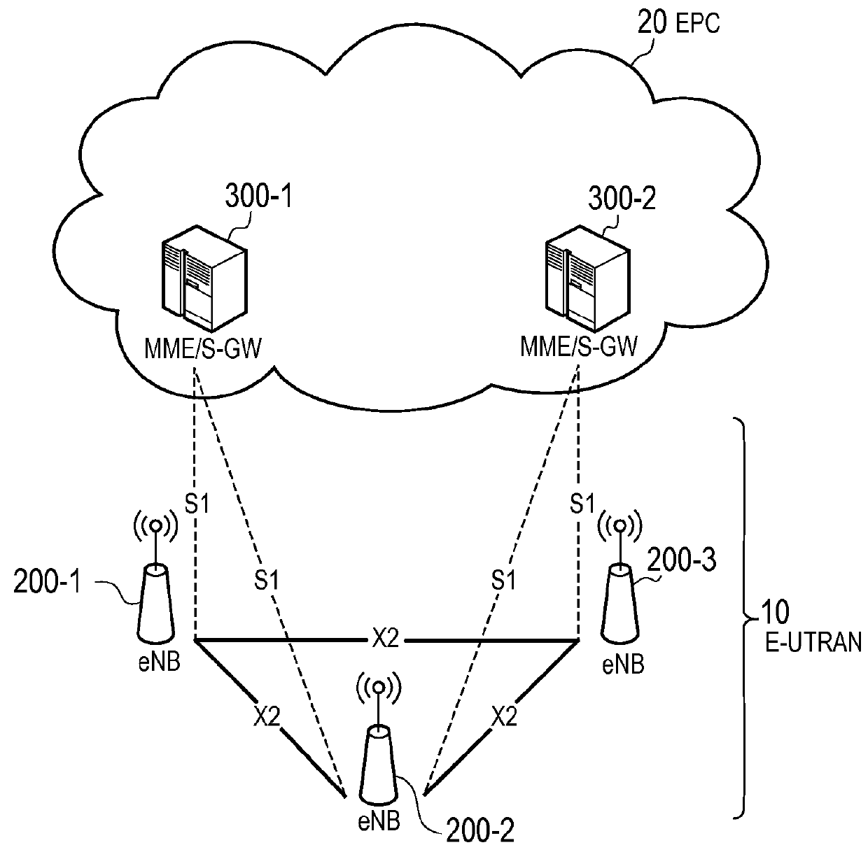
[0049]FIG. 1 is a configuration diagram of an LTE system according to the first embodiment. As shown in FIG. 1, the LTE system includes a plurality of UEs (User Equipments) 100, E-UTRAN (Evolved Universal Terrestrial Radio Access Network) 10, and EPC (Evolved Packet Core) 20. The E-UTRAN 10 corresponds to a radio access network and the EPC 20 corresponds to a core network. The E-UTRAN 10 and the EPC 20 configure a network of the LTE system.
[0050]The UE 100 is a mobile communication device and performs radio communication with a cell (a serving cell) with which a connection is established. The UE 100 corresponds to a user terminal.
[0051]The E-UTRAN 10 includes a plurality of eNBs 200 (evolved Node-Bs). The eNB 200 corresponds...
second embodiment
[0147]A second embodiment will be described below. Differences from the above embodiment will be mainly described, and the description of the same parts will be omitted as needed.
(1) Operation Outline
[0148]An operation outline according to the present embodiment will be described.
[0149]There have been described above in the first embodiment the case (the operation pattern 1) in which the MeNB 200-1 governs to perform energy saving in the PeNB 200-2 and the case (the operation pattern 2) in which the PeNB 200-2 governs to perform energy saving in the PeNB 200-2, but there will be described in the present embodiment a case in which the master eNB (Master-eNB) 200-3 governs to perform energy saving in a slave eNB (Slave-eNB) 200-4.
[0150]Herein, the master eNB 200-3 is an eNB 200 for controlling energy saving in the slave eNB 200-4. Therefore, a relationship between the master eNB 200-3 and the slave eNB 200-4 may be not only a relationship between the MeNB 200-1 and the PeNB 200-2 but ...
PUM
 Abstract
Description
Claims
Application Information