Medullary pin

a technology of medical pins and pins, applied in the field of medical pins, can solve the problems of difficult anchoring of medical pins known from the prior art, and achieve the effects of reducing design length, facilitating design, and facilitating anchoring

Active Publication Date: 2016-03-03
ORTHOFIX SRL
View PDF17 Cites 7 Cited by
  • Summary
  • Abstract
  • Description
  • Claims
  • Application Information

AI Technical Summary

Benefits of technology

[0020]Typical embodiments include a bar as the first inner part, for the fixation of the bone segment. Such a bar offers the advantage of an easy design. The bar is preferably oriented transverse to the direction of a spindle of the drive unit. Thus, the bar preferably forms a single piece with both the first inner part and the fixation means, since it is anchored directly in a middle fragment. Exemplary embodiments with multiple-piece bar comprise an inner part, typically similar to a nut, and a radially projecting bar element. For this, the bar is typically provided with a recess. This recess preferably engages by form fitting with an inner part sitting on the spindle, which is designed as a threaded element with a centrally disposed internal thread. This embodiment allows a reduction in the design length or the possibility of performing larger distraction distances.
[0021]Usually, at least one of the inner parts, typically both inner parts, have at least one through opening extending in the radial direction to acc

Problems solved by technology

One challenge in the case of medullary pins with transport of a middle fragment is principally the fixation of the ends of the medullary pin in the proximal bone frag

Method used


Image

  • Medullary pin
  • Medullary pin

Examples


Embodiment Construction

[0026]Sample embodiments shall now be described with the aid of the figures, using the same reference numbers for the same or similar parts. At times, the same or similar parts are not explained again in conjunction with each figure.

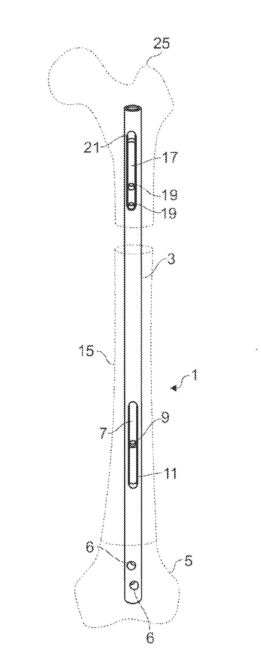
[0027]FIGS. 1 to 3 show typical embodiments of a medullary pin 1 in three different operating states. Fragments of a thigh bone are shown by broken line. These fragments are not part of the sample embodiment and serve only for illustration.

[0028]The medullary pin 1 comprises a partly hollow body 3. The body 3 is fashioned hollow throughout in the axial direction with uniform internal diameter, apart from a first end region.

[0029]Other sample embodiments of medullary pins comprise bodies having internal steps or shoulders, for example, as end stops for inner parts. In this way, displacement ranges of the inner parts can be delimited.

[0030]The body 3 has in a first end region of the body 3 locking means with which the body 3 can be locked in a first end fr...


PUM


Abstract

Medullary pin (1) for a distraction with segment transport and subsequent lengthening of a tubular bone, wherein the medullary pin (1) comprises: an at least partly hollow body (3) extending in an axial direction of the medullary pin (1), a locking means for locking the body (3) in a first end fragment (5) of the tubular bone, a first inner part (7), which is arranged displaceably in the axial direction inside the body (3) and comprises a first fixation means for the fixation of a middle fragment (15) of the tubular bone, a second inner part (17), which is arranged displaceably in the axial direction inside the body and comprises a second fixation means for the fixation of a second end fragment (25) of the tubular bone, and a drive unit (40) for the axial displacement of the first inner part (7) relative to the second inner part (17), wherein the drive unit (40) is arranged inside the body (3) between the first fixation means of the first inner part (7) and the second fixation means of the second inner part (17).

Description

BACKGROUND OF THE INVENTION[0001]The invention concerns a medullary pin for a distraction and subsequent lengthening of a tubular bone with segment transport.[0002]Medullary pins are known from the prior art, such as DE 10 2011 053 638 A1, which make possible a distraction of long tubular bones with segment transport. Two bone fragments, a distal end fragment and a proximal end fragment, are displaced relative to each other by means of a medullary pin. Furthermore, a middle bone fragment exists in applications with segment transport, also being known as the segment and likewise being part of the fractured bone. At a contact site between one of the end bone fragments and the middle fragment, bone is supposed to grow back. This is accomplished by selecting the rate of advance of the middle fragment for the distraction to be sufficiently small.[0003]Such displacements enable a treatment of major bone defects of more than 3 cm, for example, such as may occur as a result of diseases or v...

Claims


Application Information

Patent Timeline
IPC IPC(8): A61B17/72
CPCA61B2017/681A61B17/7216A61B2017/00991A61B2017/00017A61B17/7241
Inventor STAUCH, ROMAN
Owner ORTHOFIX SRL
Why Eureka
Try Eureka