Eureka AIR delivers breakthrough ideas for toughest innovation challenges, trusted by R&D personnel around the world.

Suspension Frame Structure

Active Publication Date: 2016-03-10
SUZUKI MOTOR CO LTD
View PDF10 Cites 8 Cited by
  • Summary
  • Abstract
  • Description
  • Claims
  • Application Information

AI Technical Summary

Benefits of technology

The present invention provides a suspension frame with an L-shaped reinforcement that enhances rigidity against loads from suspension arms, leading to effective suppression of deformation. This results in greater durability and stability of the suspension frame.

Problems solved by technology

However, in JP 2008-001307, since the reinforcement is arranged along a rear wall, the reinforcement can contribute to suppressing of deformation of this rear wall but cannot achieve a sufficient effect of suppressing deformation of a front wall.

Method used


Image

  • Suspension Frame Structure
  • Suspension Frame Structure
  • Suspension Frame Structure

Examples


Embodiment Construction

[0020]A preferable embodiment of the present invention will be hereinafter described in detail with reference to the attached drawings. The dimensions, materials, other specific values, and the like described in the embodiment are mere examples for facilitating understanding of the invention, and do not limit the present invention unless otherwise stated. Note that in the present specification and drawings, elements having substantially the same functions and configurations will be assigned the same reference numerals to omit redundant descriptions, and elements that are not directly related to the present invention will be omitted in the drawings.

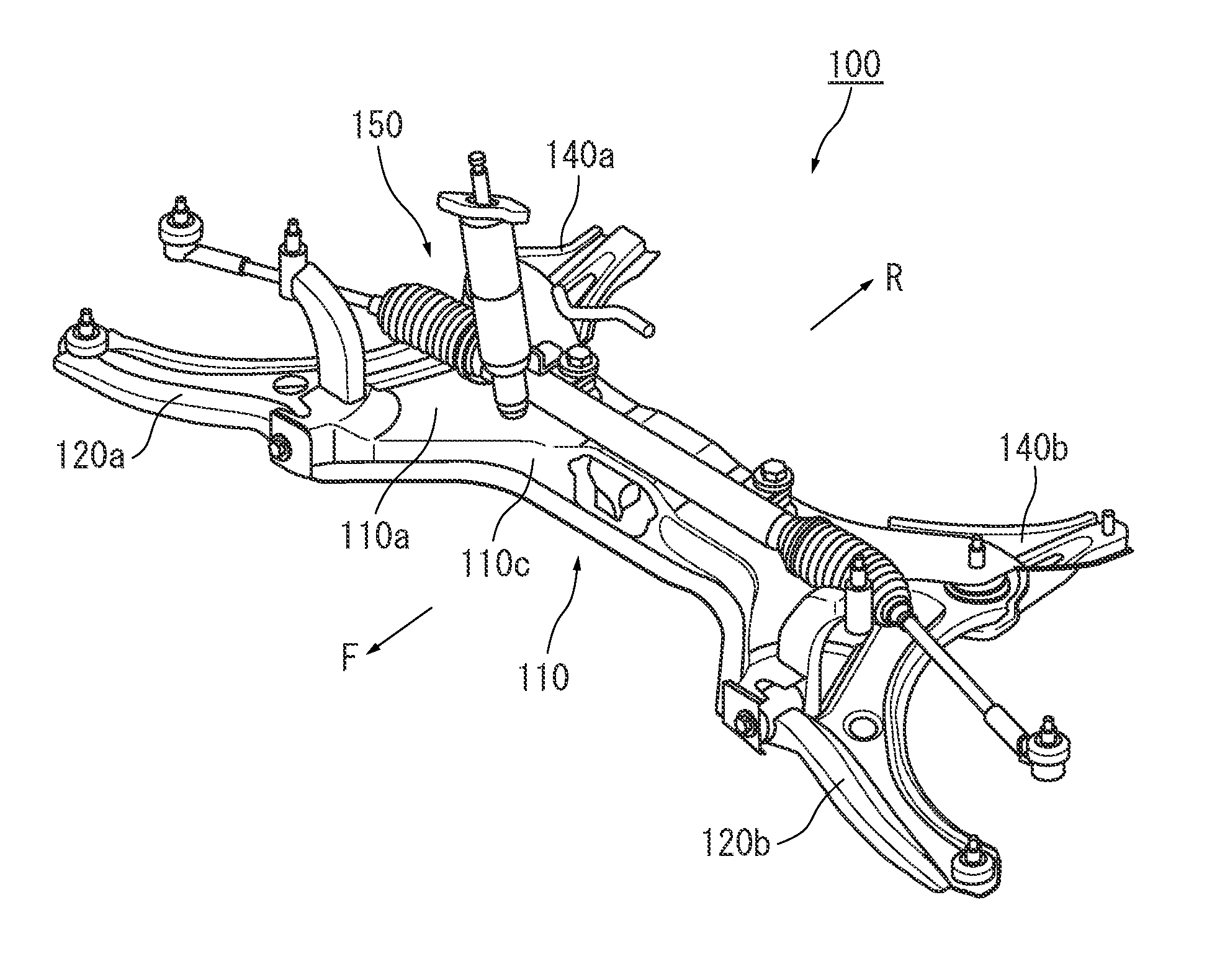
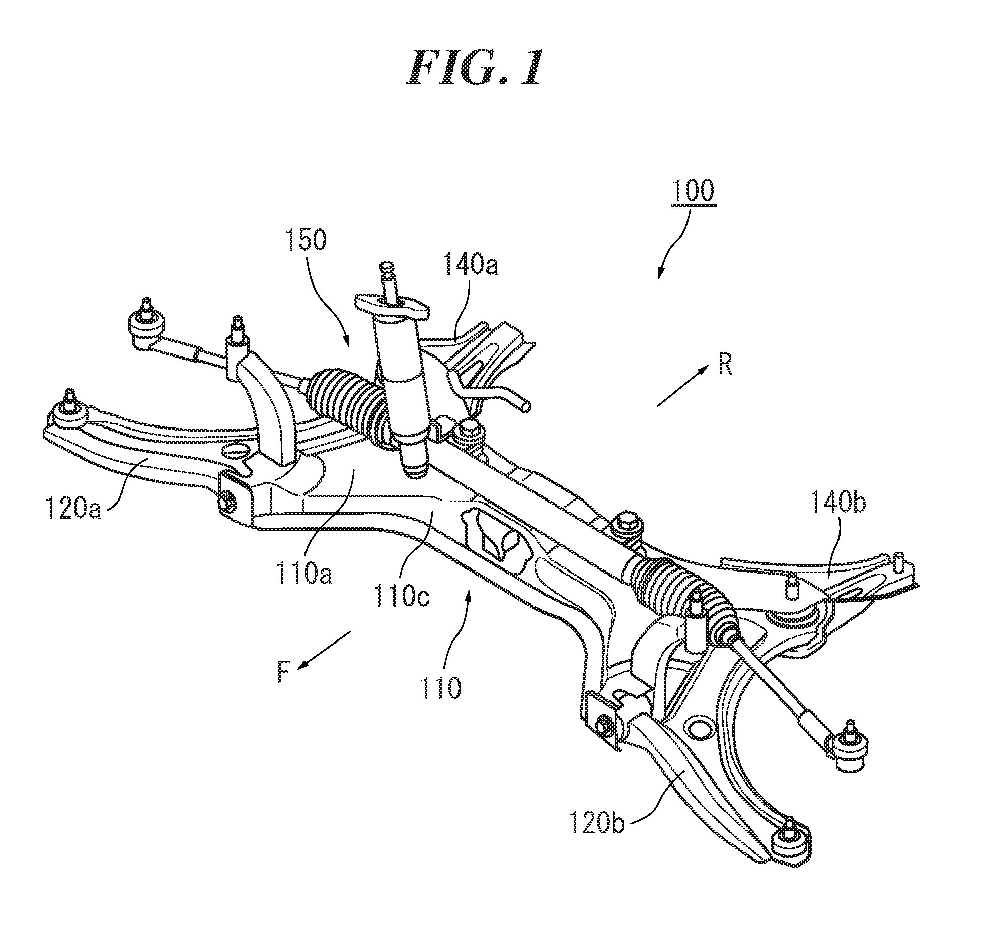
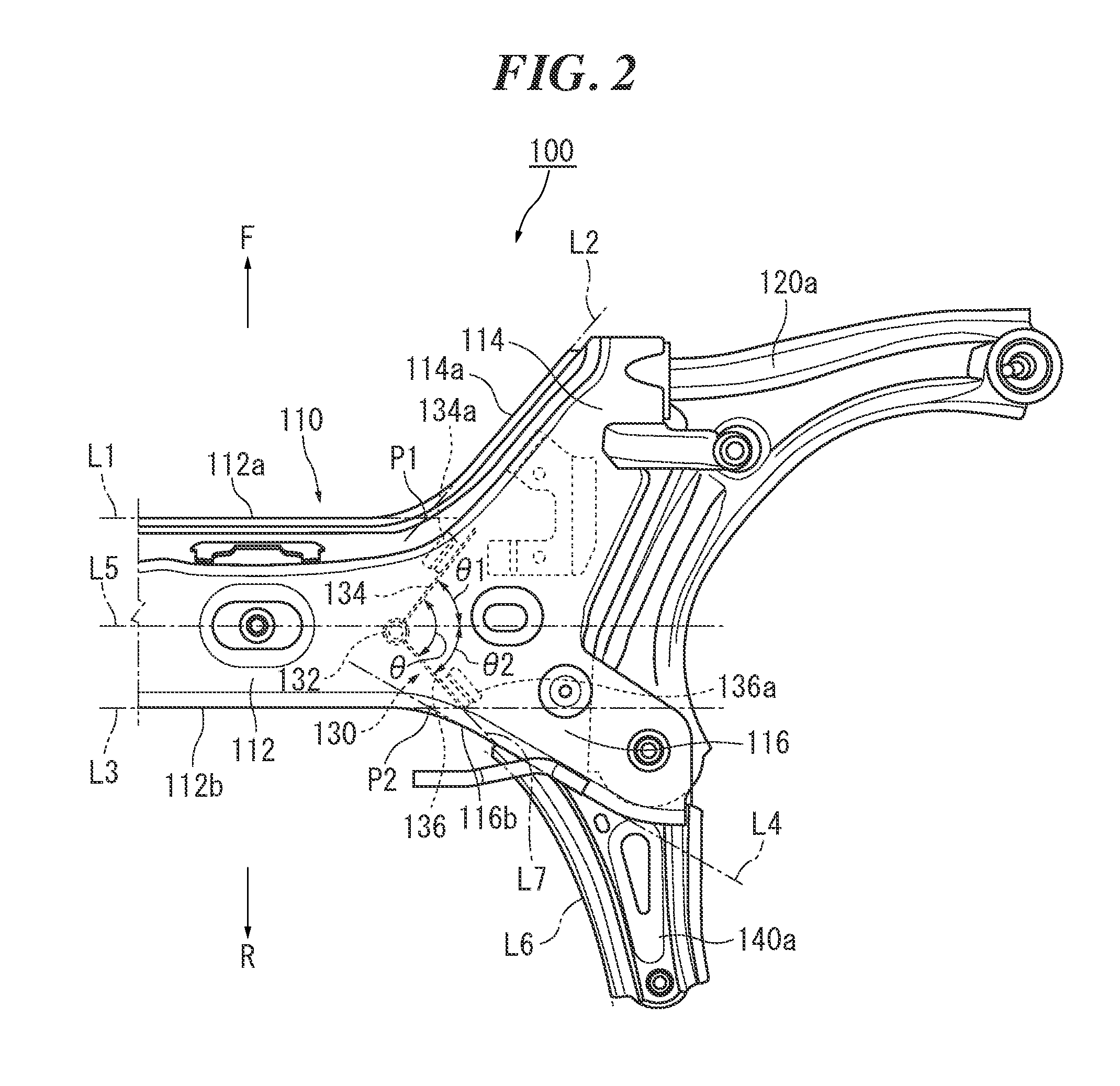
[0021]FIG. 1 is a perspective view of an overall suspension frame structure 100 according to the present embodiment. FIG. 2 is an enlarged view of a right portion of the suspension frame structure 100 in FIG. 1 as observed from above. FIG. 3 is a perspective view of the suspension frame structure 100 in FIG. 2 as observed from above on the...


PUM


Abstract

A suspension frame structure comprises a suspension frame and a reinforcement. The reinforcement has a support portion that extends in the up-down direction within the suspension frame and connects an upper wall and a lower wall of the suspension frame to each other, a front upright wall that extends outward in the vehicle-width direction and further to the front side of a vehicle from a side face of the support portion and is joined to at least one of the upper wall and the lower wall of the suspension frame, and a rear upright wall that extends outward in the vehicle-width direction and further to the rear side of the vehicle from the side face of the support portion and is joined to at least one of the upper wall and the lower wall of the suspension frame. The front upright wall and the rear upright wall form an L-shape.

Description

CROSS-REFERENCE TO RELATED APPLICATION[0001]This application is based upon and claims the benefit of priority from the prior Japanese Patent Application No. 2014-181786, filed on Sep. 5, 2014, the entire contents of which are incorporated herein by reference.FIELD[0002]The present invention relates to a suspension frame structure comprising a suspension frame that extends in a vehicle-width direction in a lower part of a vehicle and fixes suspension arms located on the outside in the vehicle-width direction, and a reinforcement arranged within the suspension frame.BACKGROUND[0003]Ordinarily, a suspension frame is attached to a vehicle so as to be spanned between a pair of left and right side members extending in the front-rear direction. Suspension arms (which are referred to also as lower arms) that suspend wheels are attached to the outside, with respect to the vehicle-width direction, of the suspension frame (e.g., JP 2008-001307). Since loads generated due to vibrations during d...

Claims


Application Information

Patent Timeline
IPC IPC(8): B60G21/055
CPCB60G21/055B60G2206/606B60G2204/15B60G2204/12B60G7/001B60G7/02B60G2204/1431B60G2206/122
Inventor MINODA, YOUSEISHOJI, TAKEHIROOZAWA, TAKAKO
Owner SUZUKI MOTOR CO LTD
Why Eureka
Eureka Blog
Learn More