
System and methods for fuel system leak detection

Inactive Publication Date: 2016-03-10
FORD GLOBAL TECH LLC
View PDF5 Cites 9 Cited by
  • Summary
  • Abstract
  • Description
  • Claims
  • Application Information

AI Technical Summary

Benefits of technology

[0003]Federal requirements for leak detection progressively become more stringent. In particular, manufacturers desiring to designate vehicles as practically zero emission vehicles (PZEVs) must prove high levels of performance both for individual vehicles and manufacturing runs of vehicles. Vehicles are required to perform leak tests with a high rate of execution, a low threshold for detection, and a high robustness. Typically, on-board sensors are used to identify situations where leak tests are likely to result in a definitive result (either pass or fail). Relaxing entry conditions to maintain a high rate of execution may reduce the robustness of a test, as EONV tests may have to be performed under less than ideal conditions.
[0004]The inventors herein have recognized the above issues and have developed systems and methods to at least partially address them. In one example, a method for a fuel system comprises indicating a leak in the fuel system based on a pressure change rate distribution during a first condition including a sealed fuel system and a pressure change rate within a threshold of zero. By indicating a leak based on a pressure change rate distribution rather than through simple thresholding, an engine-off natural vacuum test may be performed in a greater range of conditions. In this way, the execution rate of the test may be increased while maintaining or improving the leak detection rate and reducing the misclassification rate.
[0005]In another example, a method for a fuel system comprises sealing a fuel system; and executing an evaporative emissions leak test only if a duration of a fuel system pressure increase event is greater than a threshol

Problems solved by technology

Relaxing entry conditions to maintain a high rate of execution may reduce the robustness of a test, as EONV tests may have to

Method used


Image

  • System and methods for fuel system leak detection
  • System and methods for fuel system leak detection
  • System and methods for fuel system leak detection

Examples


Embodiment Construction

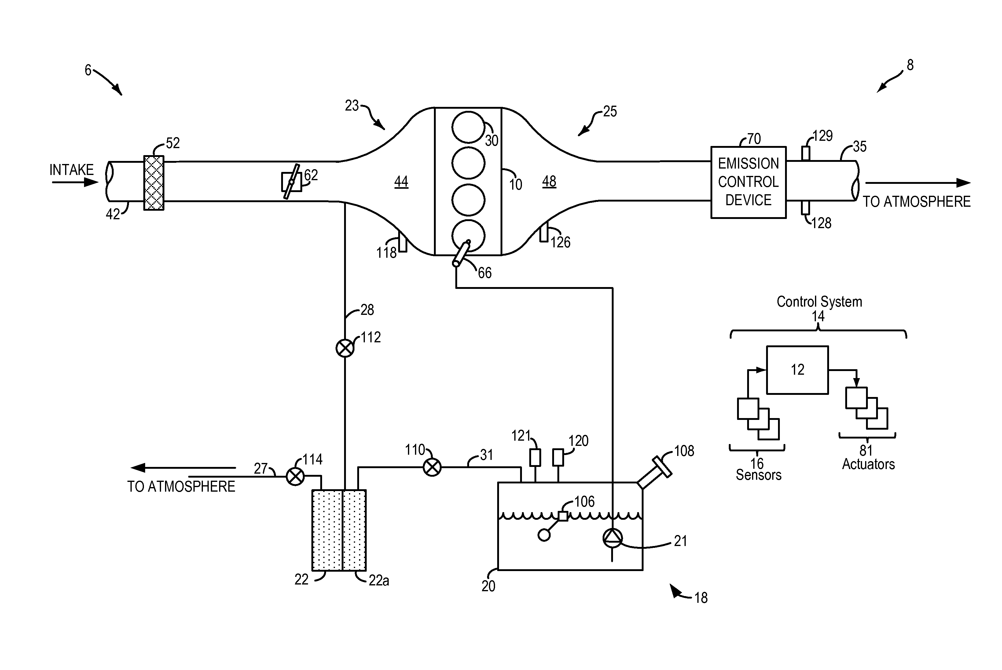
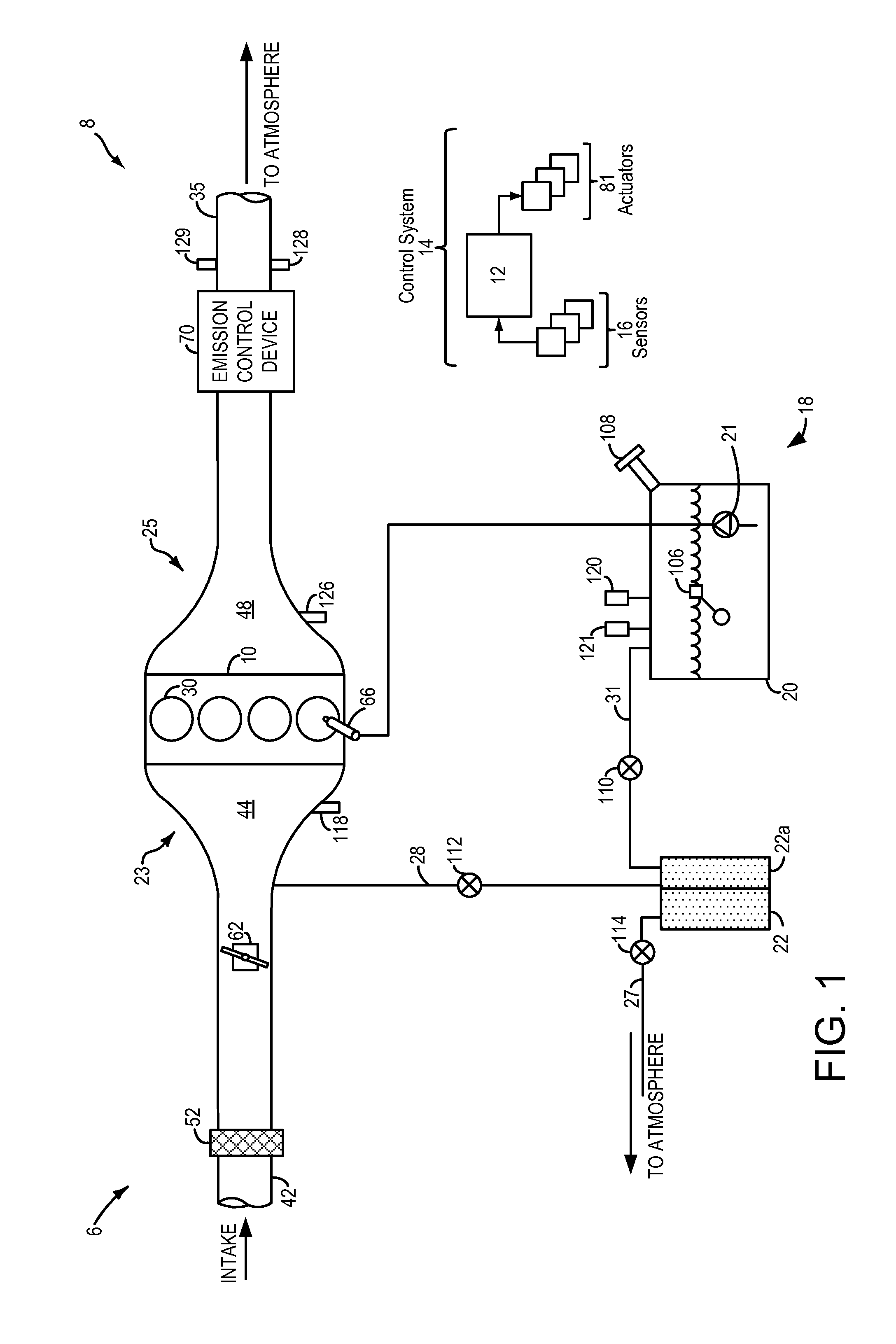
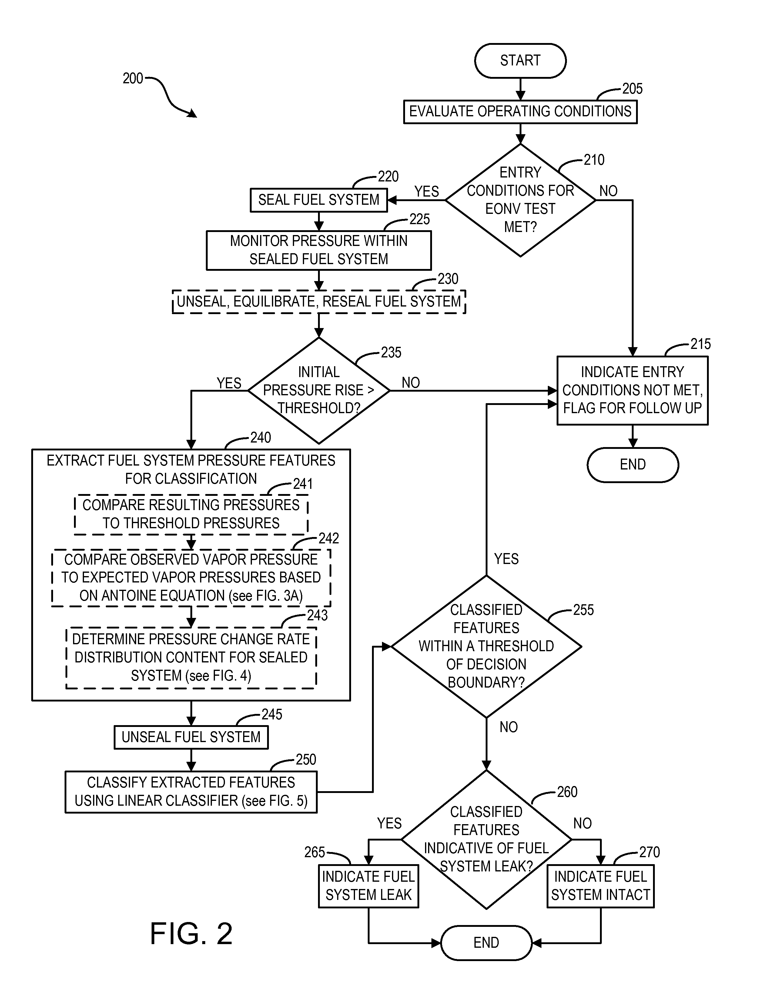
[0016]This detailed description relates to systems and methods for a vehicle fuel system. More specifically, the description relates to systems and methods for performing engine-off natural vacuum tests on a fuel system for the purpose of detecting leaks. The fuel system may be included in a hybrid vehicle system, as shown schematically in FIG. 1. FIG. 2 shows an example method for an EONV test, including the extraction of fuel system pressure features that may be classified in order to determine whether the fuel system is leaky or intact. One example fuel system pressure feature is a comparison of observed vapor pressure and expected vapor pressure based on the Antoine equation. An example method thereof is shown in FIG. 3A. FIG. 3B shows an example plot of pressure / temperature relationships for two different fuel compositions, the pressure / temperature relationships transformed by the Antoine equation. An example timeline for an EONV test including this comparison is shown in FIG. ...


PUM


Abstract

A method for a fuel system comprises indicating a leak in the fuel system based on a pressure change rate distribution during a first condition including a sealed fuel system and a pressure change rate within a threshold of zero. By indicating a leak based on a pressure change rate distribution rather than through simple thresholding, an engine-off natural vacuum test may be performed in a greater range of conditions. In this way, the execution rate of the test may be increased while maintaining or improving the leak detection rate and reducing the misclassification rate.

Description

BACKGROUND AND SUMMARY[0001]Vehicle emission control systems may be configured to store fuel vapors from fuel tank refueling and diurnal engine operations, and then purge the stored vapors during a subsequent engine operation. In an effort to meet stringent federal emissions regulations, emission control systems may need to be intermittently diagnosed for the presence of leaks that could release fuel vapors to the atmosphere.[0002]Evaporative leaks may be identified using engine-off natural vacuum (EONV) during conditions when a vehicle engine is not operating. In particular, a fuel system may be isolated at an engine-off event. The pressure in such a fuel system will increase if the tank is heated further (e.g. from hot exhaust or a hot parking surface) as liquid fuel vaporizes. As a fuel tank cools down, a vacuum is generated therein as fuel vapors condense to liquid fuel. Vacuum generation is monitored and leaks identified based on expected vacuum development or expected rates of...

Claims


Application Information

Patent Timeline
IPC IPC(8): G01M3/26
CPCG01M3/26F02M25/0809
Inventor MAKKI, IMAD HASSANTSENG, FLING FINNDUDAR, AED M.JENTZ, ROBERT ROYKUMAR, PANKAJ
Owner FORD GLOBAL TECH LLC
Learn More