Device and method for monitoring and calibrating a device for measuring the profile depth of a tyre

a technology for tyres and profiles, which is applied in the direction of vehicle testing, structural/machine measurement, instruments, etc., can solve the problems that the calibration provided by the factory cannot be seen as valid in certain circumstances, and achieve the effect of effective monitoring and calibration, effective monitoring and calibration of the measuring system, and reduced shading of the base of the depressions

Active Publication Date: 2016-03-10
BEISSBARTH AUTOMOTIVE TESTING SOLUTIONS GMBH
View PDF2 Cites 17 Cited by
  • Summary
  • Abstract
  • Description
  • Claims
  • Application Information

AI Technical Summary

Benefits of technology

[0016]Regular monitoring and calibration of the measuring device ensures a consistent measurement accuracy over the entire operating life of the measuring device.
[0030]In one embodiment, the measurement slots of the measuring modules are disposed in the rolling direction so as to be offset from one another in order to prevent said measuring modules from mutually interfering with one another. In this way, light being emitted from one illumination apparatus of a measuring module can be prevented from being captured by the image capture apparatus of another measuring module.

Problems solved by technology

As a result of the environmental factors, the mechanical suspension of the illumination apparatuses and image capture apparatuses as well as possibly of further optical elements for beam deflection, such as, e.g., mirrors or prisms, is heavily stressed, so that the factory-provided calibration can no longer be seen as valid in certain circumstances.

Method used


Image

  • Device and method for monitoring and calibrating a device for measuring the profile depth of a tyre
  • Device and method for monitoring and calibrating a device for measuring the profile depth of a tyre
  • Device and method for monitoring and calibrating a device for measuring the profile depth of a tyre

Examples


Embodiment Construction

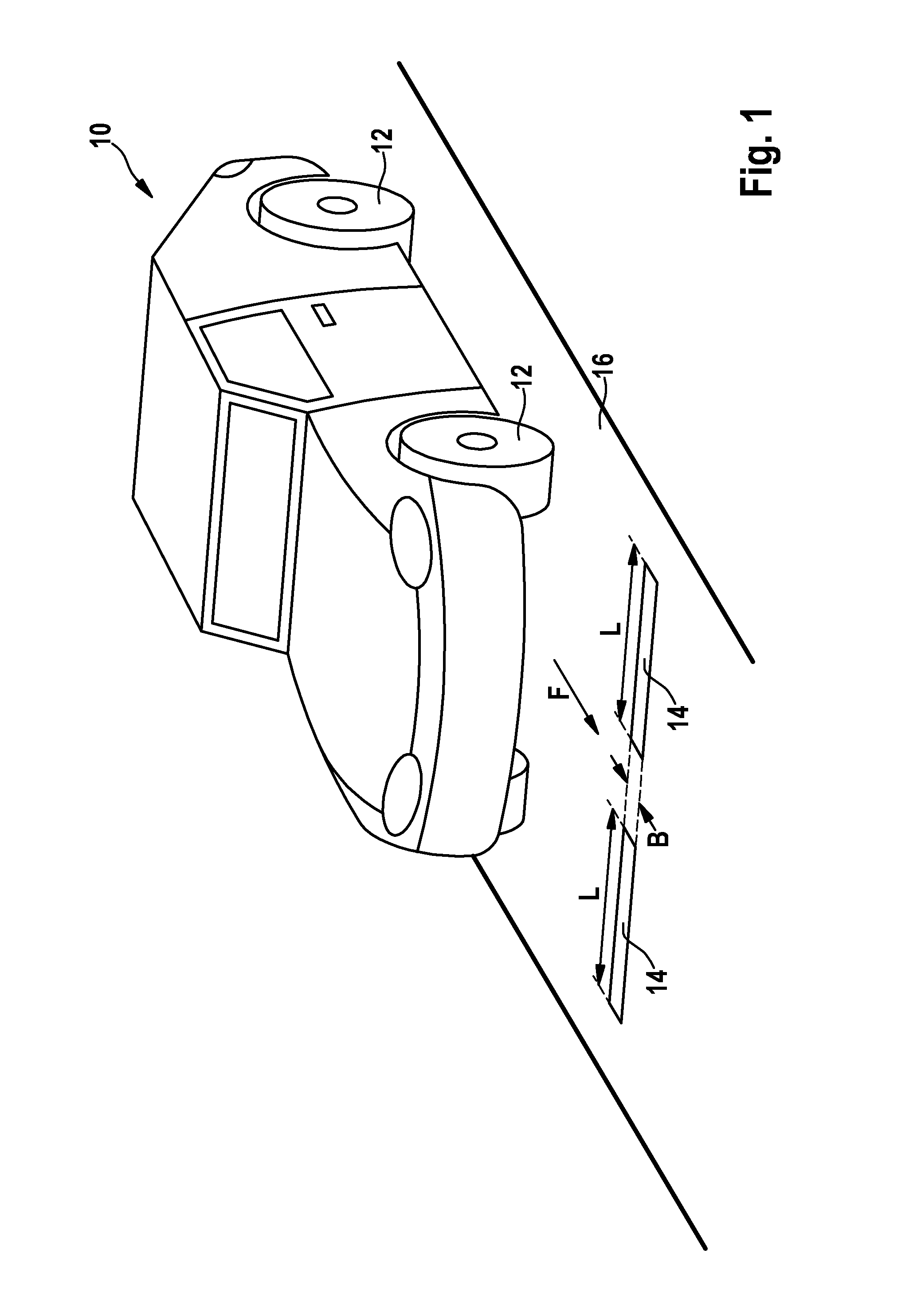
[0038]FIG. 1 shows a measuring station for measuring the profile depth of the tread of a tyre comprising a running surface 16 in which two measurement slots 14 are formed in the lane of a vehicle approaching in the direction of travel F. The measurement takes place while the vehicle comprising the wheels or, respectively, tyres thereof travels across at least one of the two oblong measurement slots 14 which are formed in the running surface 16 and are oriented in the longitudinal extension thereof transversely to the running direction of the tyres 12 of the motor vehicle 10.

[0039]The measurement slots 14 have an extension (length) L which runs transversely to the direction of travel F of the vehicle and corresponds to at least the width of the maximum contact patch of the tyres to be measured. In addition, the variance in the axles tracks of the vehicles 10 to be measured is however to be taken into account in order to make possible an automatic measurement of as large a number of d...


PUM


Abstract

A device for measuring the profile of the tread of a tyre (12) comprises: a running surface (16), which is provided for the tyre (12) to roll on and in which at least one measurement slot (14) is formed; at least one illumination apparatus (4), which is formed and arranged in such a manner that during operation it projects a plurality of light lines (6) through the measurement slot (14) onto the profile to be measured; and at least one image capture apparatus (18), which is formed to capture at least one image of at least one region of the profile to be measured. At least one monitoring and calibration device (22) is formed at at least one measurement slot (14), said monitoring and calibration device having at least one channel-shaped depression (24), which faces the illumination apparatus (4). The at least one depression (24) is formed at an angle to the plane of the running surface (16), which is parallel to the direction of a light beam, which in the proper state is emitted by the illumination apparatus (4) and is incident into the depression (24).

Description

BACKGROUND OF THE INVENTION[0001]The invention relates to a device and a method for monitoring and calibrating a device for measuring the profile depth of a tyre, in particular of a motor vehicle tyre.[0002]In order to measure the profile depth of tyres, different methods for manually or automatically measuring the profile depth are known, which comprise methods for measuring in a mechanical or non-contact manner as well as methods for measuring a stationary or rolling vehicle or, respectively, tyre.[0003]Triangulation methods using laser scanners for measuring profile depth on a roller chassis dynamometer are described, for example, in the German patent specification DE 197 05 047 A1 and the European patent specification EP 1 394 503 B1.[0004]The German patent specification DE 10 2006 062 447 A1 likewise measures a region of the tyre profile while the tyre rolls over an opening by means of a light section triangulation method. The method provides that an illumination line is guided...

Claims


Application Information

Patent Timeline
Patent Type & Authority Applications(United States)
IPC IPC(8): G01M17/02G01B11/24
CPCG01B11/24G01M17/027G01B11/22G01B11/25
Inventor UFFENKAMP, VOLKERNOBIS, GUENTER
Owner BEISSBARTH AUTOMOTIVE TESTING SOLUTIONS GMBH
Why Eureka
Try Eureka