Differential pressure gauge

a pressure gauge and differential pressure technology, applied in the direction of fluid pressure measurement by mechanical elements, instruments, measurement devices, etc., can solve the problems of not being reacted correctly, affecting the measuring accuracy of differential pressure gauges, etc., to achieve the effect of eliminating

Inactive Publication Date: 2012-04-03
SAILSORS INSTR BEIJING
View PDF10 Cites 5 Cited by
  • Summary
  • Abstract
  • Description
  • Claims
  • Application Information

AI Technical Summary

Benefits of technology

[0007]An object of the present invention is to provide a differential pressure gauge, which adopts the double-spring balance principle, thereby effectively eliminating the problems of zero drift and linear difference which are produced by the single spring.

Problems solved by technology

This will affect the measuring accuracy of the differential pressure gauge.
Its connection of the diaphragm's central axis and the leaf spring will affect the movement of the diaphragm so that it can not be reacted correctly.
It will affect the measuring accuracy of the differential pressure gauge.
Its way to adjust the range is complex and the adjusting point is inside of the differential pressure gauge.

Method used


Image

  • Differential pressure gauge
  • Differential pressure gauge
  • Differential pressure gauge

Examples


Embodiment Construction

[0040]The present invention is further explained with the accompanying drawings.

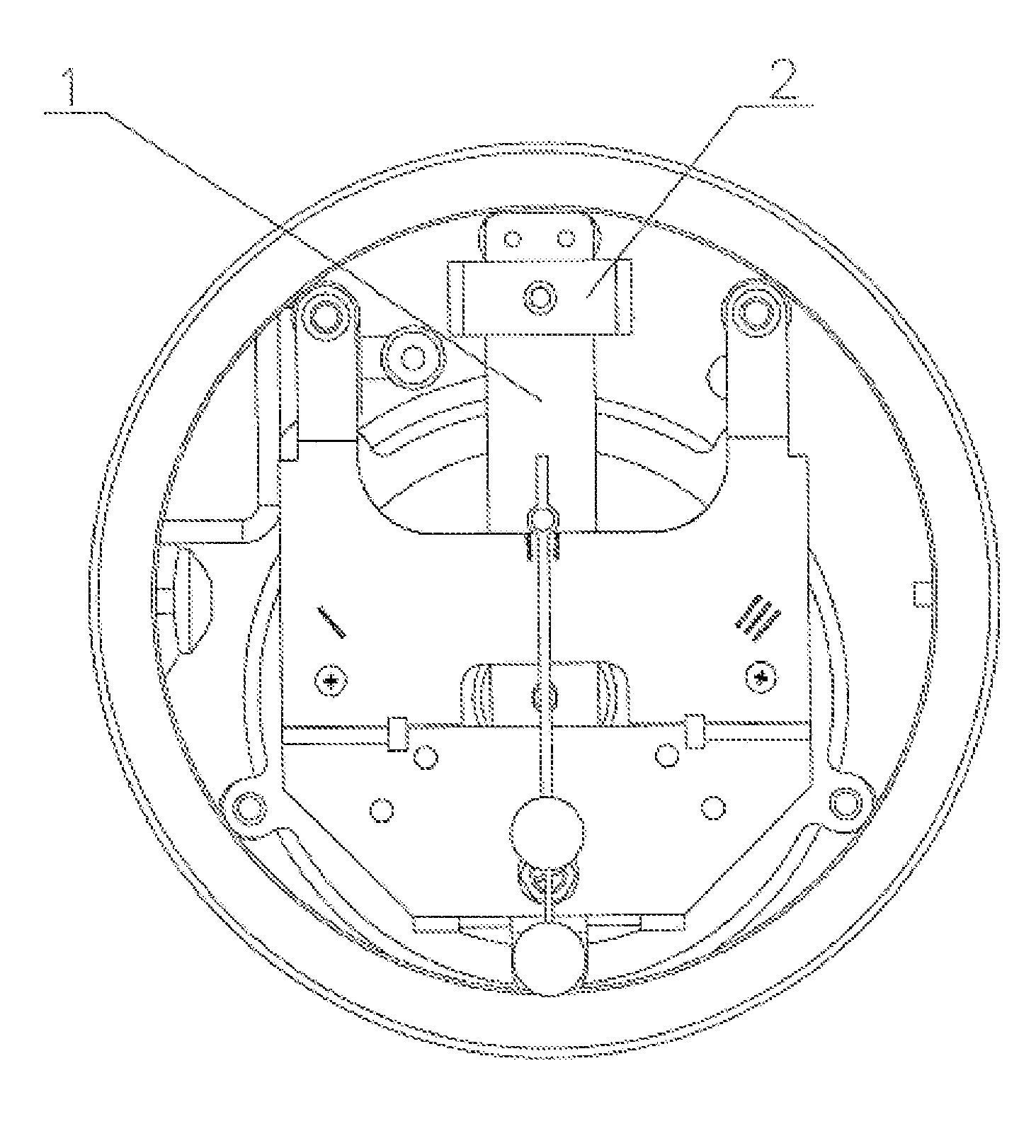
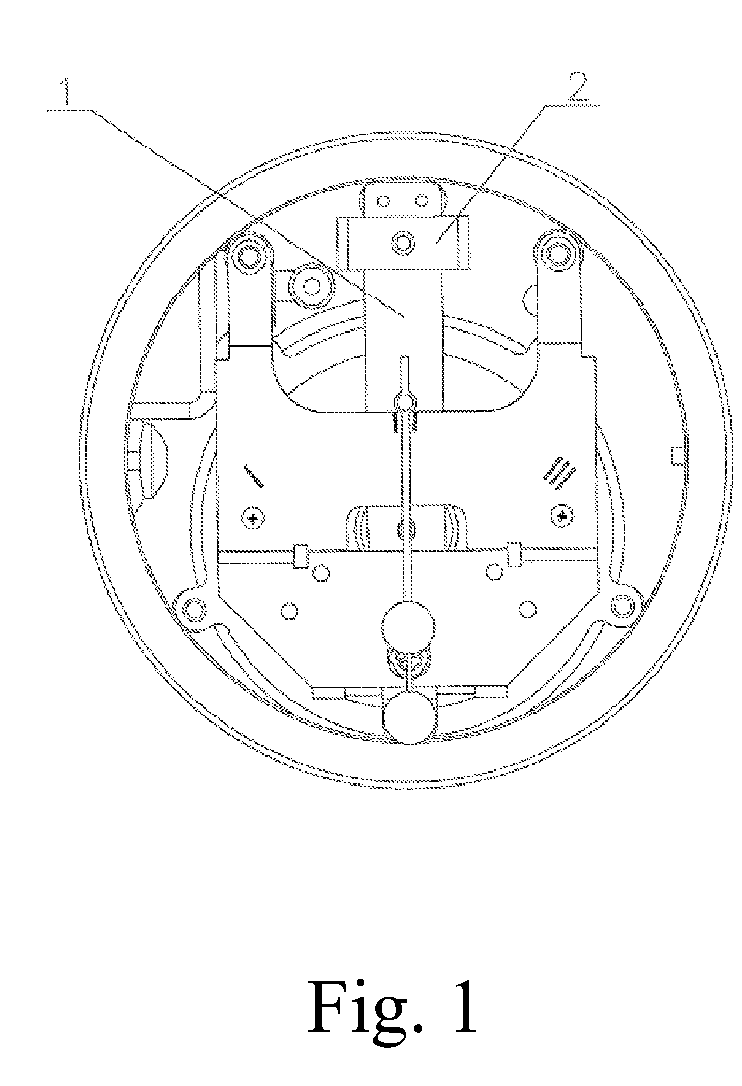
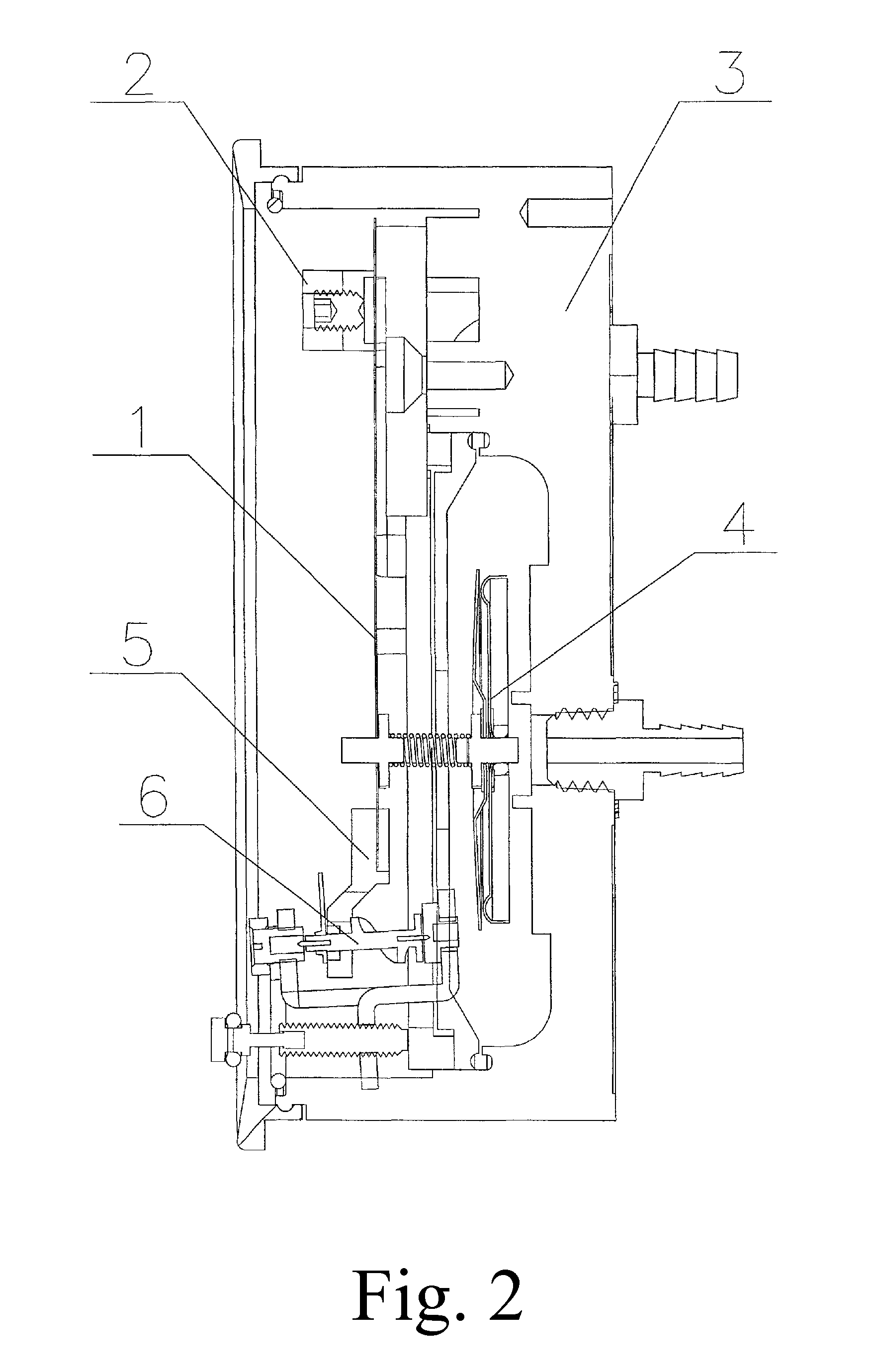
[0041]Referring to FIGS. 1 to 5 of the drawings, an external range adjusting device of a differential pressure gauge according to a preferred embodiment of the present invention is illustrated, wherein the external range adjusting device comprises an adjusting spring 7, a balance spring 10, an adjusting screw 8 and a slider 9. The adjusting spring 7 is provided at a lower end of a measuring diaphragm 4 as a sensitive element. The balance spring 10 is provided at an upper end of the measuring diaphragm 4. The adjusting screw 8 and the slider 9 are provided at a lower end of the adjusting spring 7. A diaphragm cover 11 is provided at an upper end of the balance spring 10.

[0042]The adjusting spring 7 at the lower end of the measuring diaphragm 4 can be compressed by the upper and lower displacement of the slider 9, which is driven by the adjusting screw 8 at the outside of the housing 3, thus affecting the ...


PUM

PropertyMeasurementUnit
magneticaaaaaaaaaa
pressureaaaaaaaaaa
transparentaaaaaaaaaa

Abstract

A differential pressure gauge includes a housing, a leaf spring having a magnetic steel, a measuring diaphragm, a helix, a dial, a range adjusting device and a diaphragm cover. The measuring diaphragm is connected with the leaf spring by connectors. The range adjusting device includes an adjusting spring provided at a lower end of the measuring diaphragm, a balance spring provided at an upper end of the measuring diaphragm, an adjusting screw and a slider which are provided at a lower end of the adjusting spring. The adjusting end of the adjusting screw is provided outside of the housing. The adjusting spring can be compressed by the upper and lower displacement of the slider driven by the adjusting screw, thus affecting the rigidity of the system to change the range of the differential pressure gauge. The differential pressure gauge facilitates adjusting the range and has the accurate measurement.

Description

BACKGROUND OF THE PRESENT INVENTION[0001]1. Field of Invention[0002]The present invention relates to a differential pressure gauge.[0003]2. Description of Related Arts[0004]Mechanical differential pressure gauge is an elastic pressure gauge which makes use of easy and frictionless magnetic spiral movement and measures by the rubber diaphragm as the sensing element. When the differential pressure (including positive and negative pressure) acts on the diaphragm, the diaphragm will be out of shape to displace the center thereof. Connector drives the leaf spring which has the magnetic steel to move. Under the magnetic induction, the helix, which has the pointer thereon, will turn around so that the pointer will indicate the pressure value to achieve the aim of measurement.[0005]FIGS. 1 and 2 show a conventional differential pressure gauge whose housing 3 is round. Its helix 6 uses the independent bracket. The central axis of the measuring diaphragm 4 and the leaf spring 1 are connected ...

Claims


Application Information

Patent Timeline
Patent Type & Authority Patents(United States)
IPC IPC(8): G01L13/02
CPCG01L7/084G01L7/088G01L13/025G01L19/16
Inventor LI, YANFENGLI, HONGYA
Owner SAILSORS INSTR BEIJING
Why Eureka
Try Eureka