Flow conditioner for a fluid transport pipe

a technology of flow conditioner and fluid transport pipe, which is applied in the direction of service pipe system, liquid/fluent solid measurement, process and machine control, etc., can solve the problems of few conditioners that reduce the swirl of the gas stream in satisfactory manner, the sensitive of the spinner gas volume meter installed in the delivery station, and the risk of interruption of continuity, so as to avoid the risk of interruption. , the effect of reducing the drawback

Active Publication Date: 2005-08-18
GRTGAZ
View PDF12 Cites 34 Cited by
  • Summary
  • Abstract
  • Description
  • Claims
  • Application Information

AI Technical Summary

Benefits of technology

[0008] The present invention thus seeks to mitigate such drawbacks by proposing a compact flow conditioner which enables all flow disturbances to be eliminated effectively, while avoiding any risk of interrupting continuity in fluid feed.
[0020] Preferably, the moving ring includes at least one adjustable abutment element for holding the bypass passage open in the event of the porous plate becoming clogged. This makes it possible to avoid a phenomenon of self-sustained oscillations in the moving ring which would have a harmful effect on the quality of metering.

Problems solved by technology

The spinner gas volume meters that are installed in delivery stations are sensitive to conditions of use.
In particular, when such meters are installed downstream from expanders or from obstacles such as valves, bends, double bends, constrictions, T-junctions, or other non-rectilinear elements, their accuracy can be affected by the disturbances generated by such obstacles.
Nevertheless, very few conditioners reduce in satisfactory manner the swirl of the gas stream, its asymmetry, and the pulses in the flow.
They are designed to be used with straight line lengths upstream and downstream that correspond to several times the nominal diameter of the pipe, which makes them of limited usefulness when it is desired to make compact expander and metering stations.
Nevertheless, there exists a risk of the porous plate in such a flow conditioner becoming clogged, which would lead to a large increase in head loss, and above all to an interruption in gas feed continuity.
Such clogging could arise in exceptional manner, in particular when the impurities present in the gas close up the pores in the porous plate.

Method used


Image

  • Flow conditioner for a fluid transport pipe
  • Flow conditioner for a fluid transport pipe
  • Flow conditioner for a fluid transport pipe

Examples


Embodiment Construction

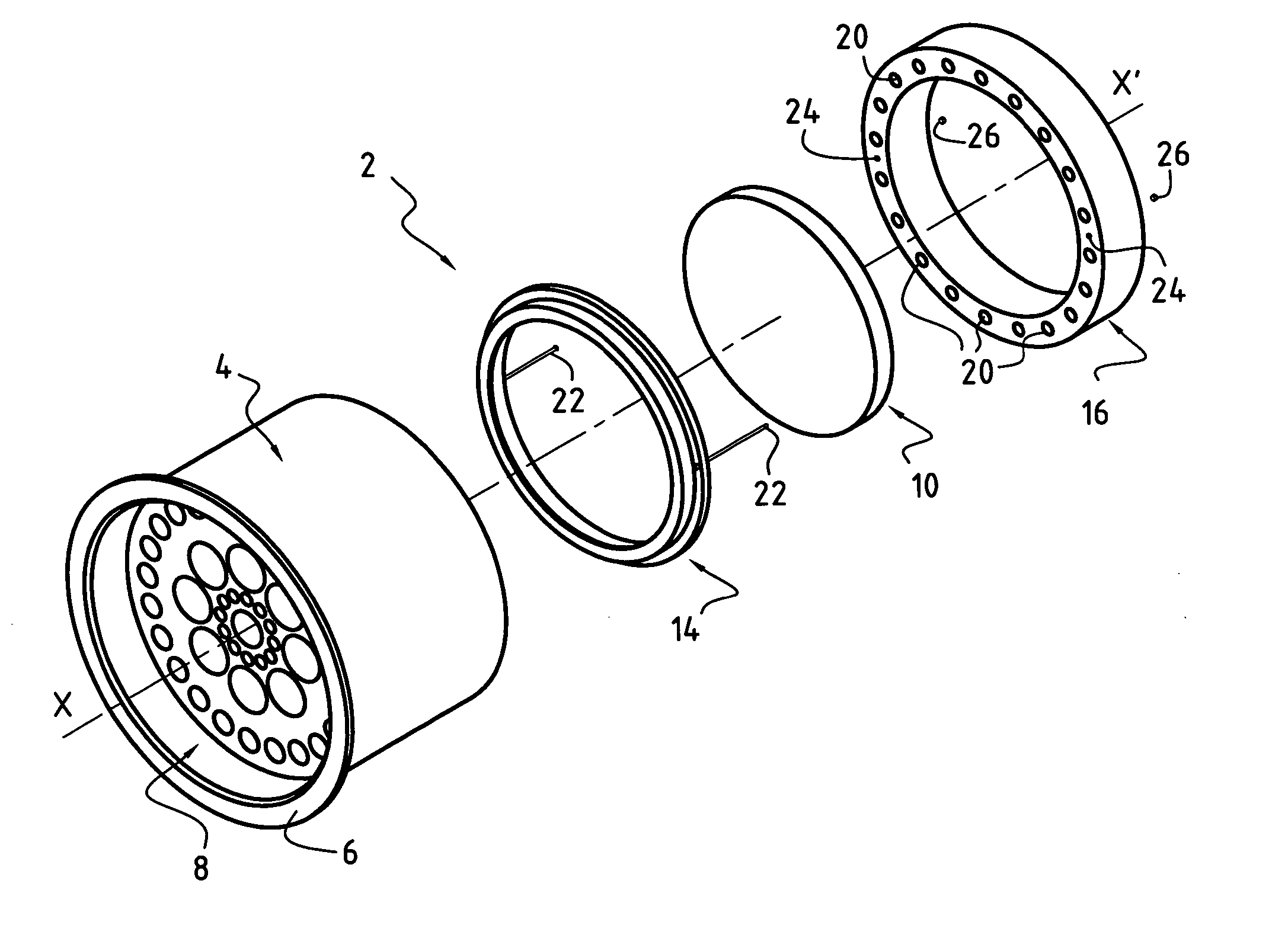
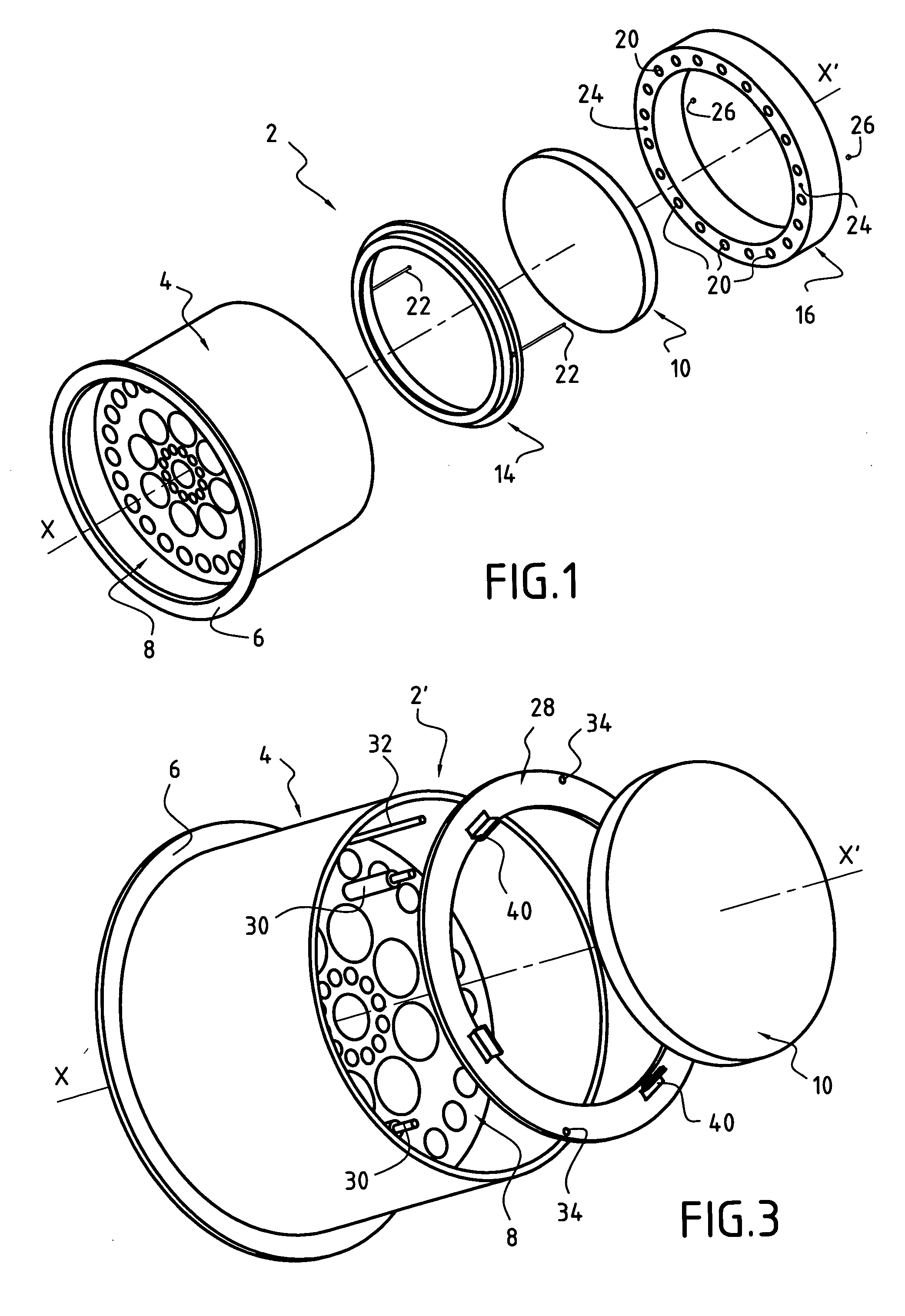
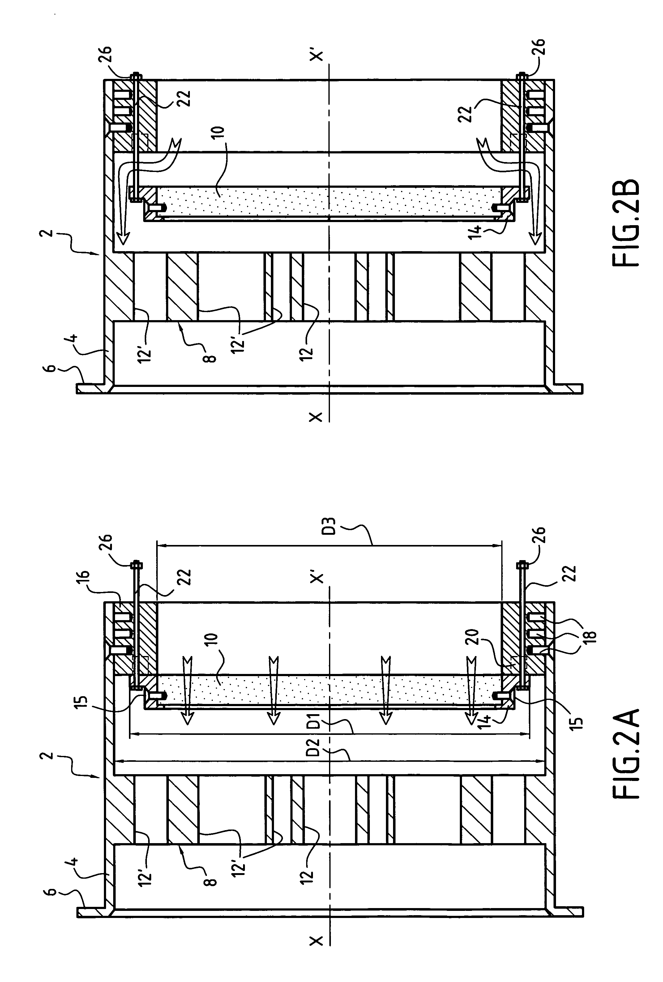
[0031] In the figures, the flow conditioner 2, 2′ is for use in gas transport pipes. In general, the present invention applies to flow conditioners for pipes for transporting any type of fluid.

[0032] The flow conditioner 2, 2′ essentially comprises a tubular main body 4 of axis XX′ constituting a support. At its downstream end, the main body 4 has a flange 6 enabling it to be secured to a gas transport pipe (not shown). The main body 4 is disposed inside the pipe so that its axis XX′ coincides with the axis of the pipe.

[0033] The conditioner 2, 2′ also comprises at least one flow rectifier 8 disposed inside the main body 4 essentially perpendicularly to its axis XX′, and a porous plate 10 disposed inside the main body 4 upstream from the flow rectifier 8 and parallel thereto.

[0034] As shown in the figures, the flow rectifier may be a perforated plate 8 held securely to the inside of the main body 4. For example it may be formed integrally with the main body 4. It further includes...


PUM

PropertyMeasurementUnit
thicknessaaaaaaaaaa
distanceaaaaaaaaaa
thicknessaaaaaaaaaa

Abstract

The flow conditioner for a fluid transport pipe, comprises a support-forming substantially tubular main body, at least one flow rectifier disposed inside the main body essentially perpendicularly to the axis XX′ thereof, and a porous plate disposed inside the main body upstream from the flow rectifier and parallel thereto. The elements of the conditioner are disposed in such a manner that a substantial fraction of the fluid flow passes through the flow rectifier and the porous plate in the absence of the porous plate becoming clogged. A bypass circuit is provided to ensure fluid flow continuity in the event of the porous plate becoming clogged.

Description

BACKGROUND OF THE INVENTION [0001] The present invention relates to the general field of flow conditions for fluid transport pipes. It relates more particularly to a flow conditioner for a gas transport pipe, the conditioner including at least one flow rectifier associated with a porous plate located upstream from the flow rectifier. [0002] The spinner gas volume meters that are installed in delivery stations are sensitive to conditions of use. In particular, when such meters are installed downstream from expanders or from obstacles such as valves, bends, double bends, constrictions, T-junctions, or other non-rectilinear elements, their accuracy can be affected by the disturbances generated by such obstacles. [0003] In order to eliminate those disturbances, it is known to provide spinner meters with flow conditioners. Such equipment serves to attenuate the flow disturbances such as rotation of the gas stream, known as “swirl”, jet effects, or acoustic pulses, over distances that are...

Claims


Application Information

Patent Timeline
Patent Type & Authority Applications(United States)
IPC IPC(8): F16L55/027
CPCF16L55/02718F16L55/027Y10T137/8049Y10T137/8122Y10T137/87539
Inventor CANCADE, JULIENBECCAT, JEAN-LUC
Owner GRTGAZ
Why Eureka
Try Eureka