
Timepiece

Active Publication Date: 2016-03-10
SEIKO INSTR INC
View PDF15 Cites 1 Cited by
  • Summary
  • Abstract
  • Description
  • Claims
  • Application Information

AI Technical Summary

Benefits of technology

The present invention provides a timepiece that can rotate the operation member while still preventing malfunctions of the display body. It also ensures high reliability in waterproof performance around the operation member.

Problems solved by technology

In this operation, when the frictional engagement force is strong, the rotational operation of the operation member becomes heavy.
Moreover, with the rotation of the operation member, the outer periphery of the waterproof member slides on the inner peripheral surface of the pipe, so that the wear of this waterproof member is promoted.
Thus, wear component (hereinafter referred to as wear refuse) is accumulated between the waterproof member and the pipe inner peripheral surface, so that there is a fear of deterioration in waterproof performance.

Method used


Image

  • Timepiece
  • Timepiece
  • Timepiece

Examples


first embodiment

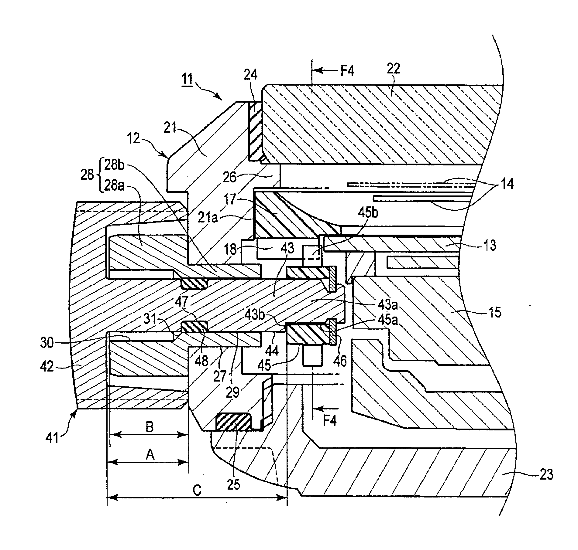
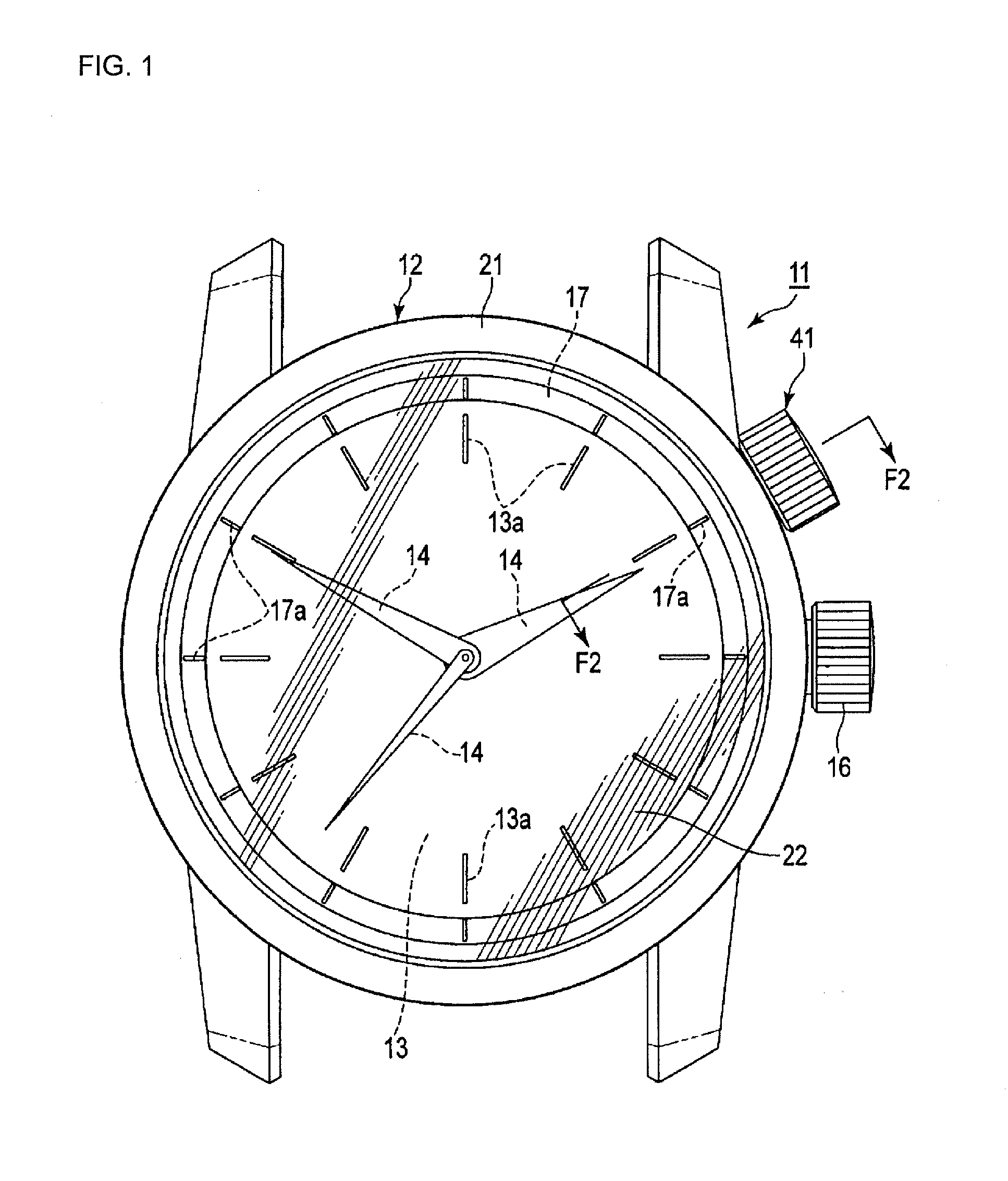
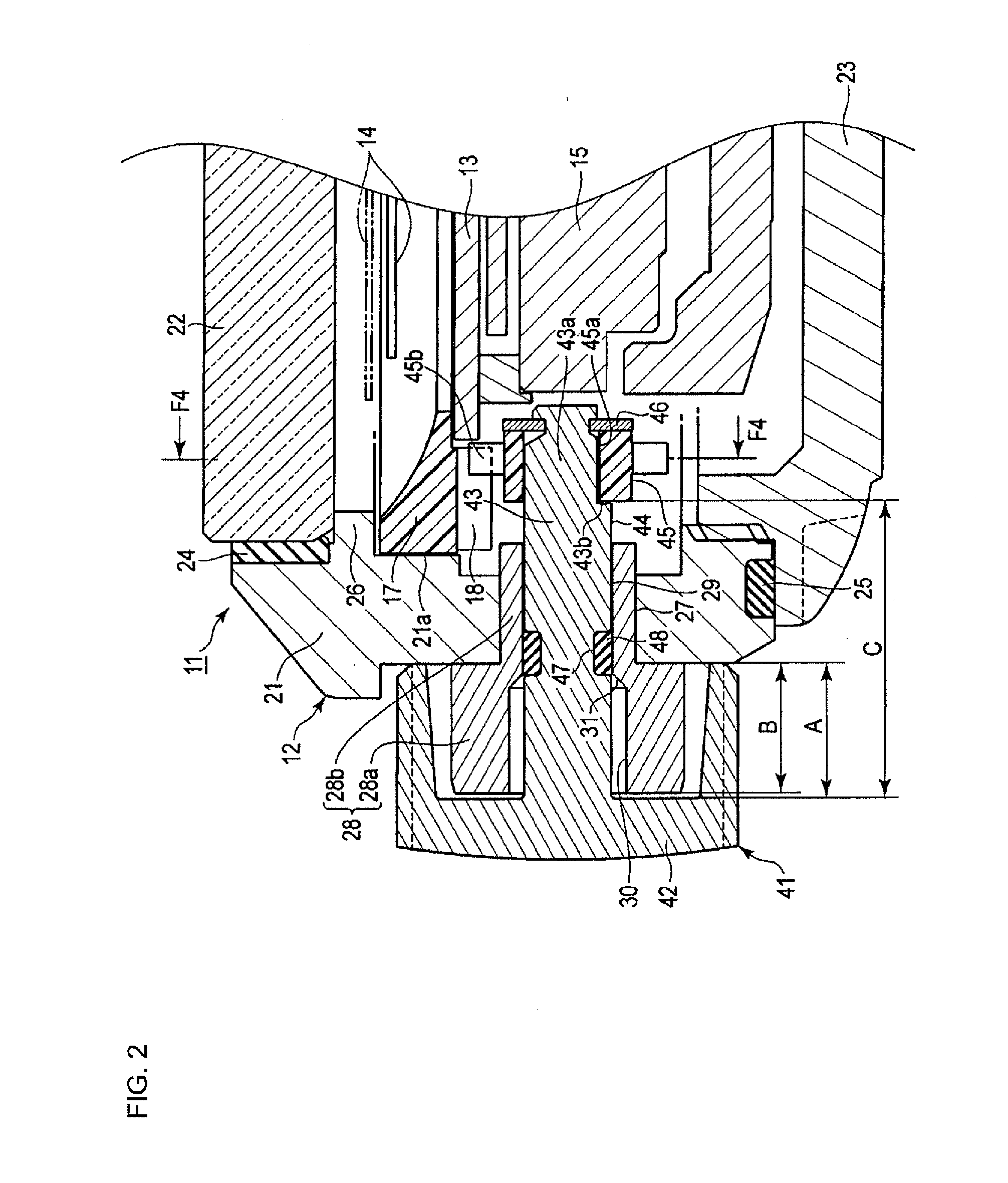
[0040]the present invention will be described with reference to FIGS. 1 through 4.

[0041]In FIGS. 1 through 3, numeral 11 indicates a timepiece such as a portable timepiece, more specifically, a waterproof wristwatch. The wristwatch 11 is equipped with a case 12 constituting the exterior member thereof.

[0042]As shown in FIGS. 2 and 3, in the case 12, there are accommodated requisite members such as a dial 13, a movement 15 controlling the movement of the time display hands 14, and a display body 17.

[0043]The dial 13 is circular, and has in the peripheral portion a time indicating scale 13a shown in FIG. 1. The dial 13 may be a digital display type dial which displays the time display scale through a liquid crystal screen. Of a time hand, a minute hand, and a second hand, the time display hands 14 at least consist of the time hand and the minute hand.

[0044]As shown in FIG. 1, a crown 16 is mounted to the case 12 in the 3 o'clock direction of the wristwatch 11. The crown 16 is rotated ...

second embodiment

[0088]Next, the procedures for rotating the display body 17 in the second embodiment will be described.

[0089]First, in the state (shown in FIG. 6) in which the packing 48 is in contact with the first annular contact surface 29 constituting the inner peripheral surface of the small-diameter portion 28b of the pipe 28, the head portion 42 of the operation member 41 is pinched by the fingers, and the operation member 41 is pushed in toward the interior of the case 12 against the urging force of the coil spring 49, arranging the operation member 41 at the operating position as shown in FIG. 7. This pushing-in operation is stopped when the peripheral wall of the head portion 42 comes into contact with the outer side surface 21b of the case band 21.

[0090]Through this movement of the operation member 41, the packing 48 gets out of the narrow gap between the shaft portion 43 and the inner peripheral surface of the small-diameter portion 28b, and gets into the wide gap between the shaft port...


PUM


Abstract

Provision of a timepiece which, although it can suppress a malfunction of the display body in the case, can lightly rotate the operation member causing the display body to operate in conjunction therewith, and which exhibits high level of reliability in waterproof performance around the operation member. To a case 12 to which a pipe 28 is fixed, there is mounted an operation member 41 conjunction-moving a display body 17 in the case 12 so as to be movable between an operating position and a setting position. One of the pipe 28 and a shaft portion 43 of the operation member 41 inserted into the same has a first annular contact surface 29, and a second annular contact surface 30 forming a diameter different from the diameter that the contact surface 29 forms, and an annular slope 31 extending between these contact surfaces. The other has an annular opposing surface 44 opposite each of the above surfaces. A packing 48 capable of elastic deformation and configured to effect waterproofing between the pipe 28 and the shaft portion 43 is mounted to the other so as to protrude from the annular opposing surface 44. At the operating position, the packing 48 is brought into contact with the annular contact surface forming a wide gap between itself and the annular opposing surface 44, and, at the setting position, the packing 48 is brought into contact with the annular contact surface forming a narrow gap between itself and the annular opposing surface 44.

Description

RELATED APPLICATIONS[0001]This application claims priority under 35 U.S.C. §119 to Japanese Patent Application No. 2014-183402 filed on Sep. 9, 2014, the entire content of which is hereby incorporated by reference.1. FIELD OF THE INVENTION[0002]The present invention relates to a timepiece such as a portable timepiece containing within a case a display body moved through operation outside the case constituting the exterior member.2. DESCRIPTION OF THE RELATED ART[0003]Conventionally, there has been known a timepiece equipped with an in-revolving ring arranged so as to be rotatable around the peripheral edge of the dial in the exterior case, and an operation member rotating this ring from the outside of the exterior case (See, for example, JP-A-2010-139399 (Patent Literature 1)).[0004]In the timepiece of Patent Literature 1, the operation member causing the in-revolving ring to rotate in conjunction therewith has a shaft portion extending through a pipe fixed to the exterior case, and...

Claims


Application Information

Patent Timeline
IPC IPC(8): G04B37/10G04B3/04
CPCG04B3/041G04B37/106G04B19/283G04B37/08G04B37/081G04B37/103G04B37/082G04B37/10
Inventor HIRANUMA, HARUKIISHIDA, MASAHIRO
Owner SEIKO INSTR INC
Learn More