Power supply, lighting device, headlight device and vehicle
a technology of headlight device and power supply, which is applied in the direction of semiconductor devices for light sources, lighting and heating apparatus, transportation and packaging, etc., can solve the problems of fan rotation speed reducing or stopping rotation, headlight device malfunction, rotation malfunction being detected in error
- Summary
- Abstract
- Description
- Claims
- Application Information
AI Technical Summary
Benefits of technology
Problems solved by technology
Method used
Image
Examples
embodiment 1
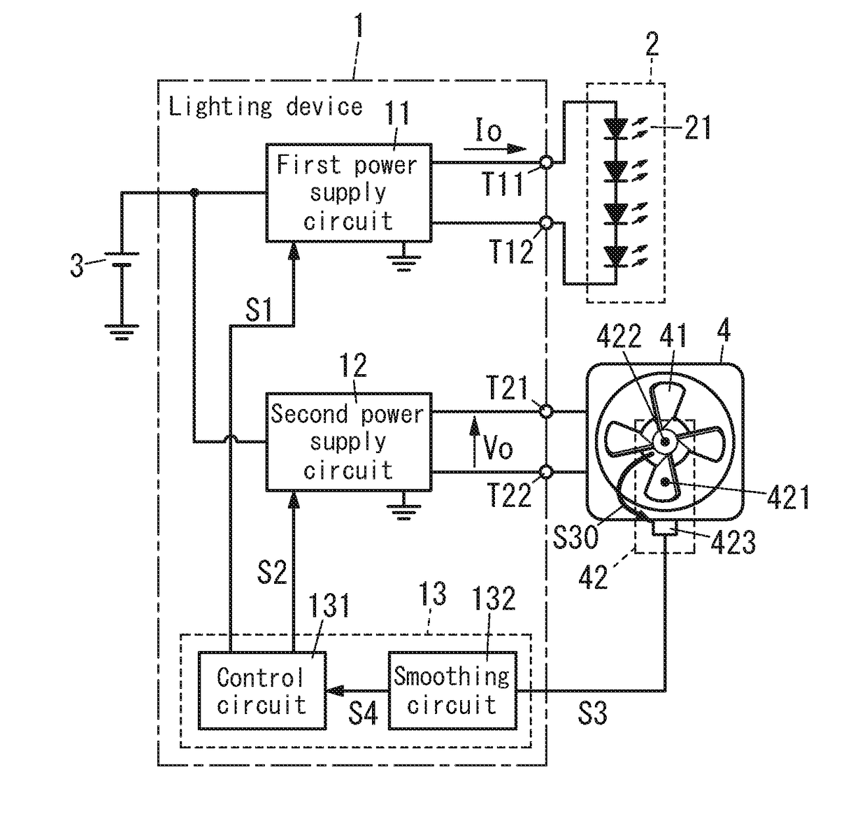
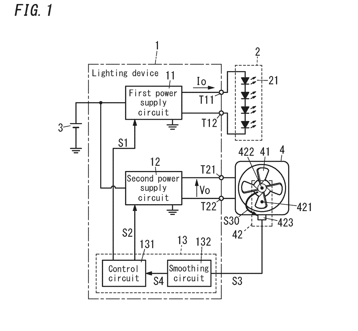
[0026]FIG. 1 shows a block diagram of a lighting device 1 according to Embodiment 1.
[0027]The lighting device 1 includes a first power supply circuit 11, a second power supply circuit 12 and an output adjustment circuit 13.
[0028]The first power supply circuit 11 is configured to provide a lighting load 2 with first electric power. Preferably, the lighting load 2 includes LEDs 21 as a light source and is configured to be lit by the first electric power. Specifically, the first power supply circuit 11 may receive DC power from a DC power supply 3 such as a battery to provide the lighting load 2 with DC power as the first electric power. For example, the first power supply circuit 11 is composed of a current adjustment circuit, and will operate so as to cause a load current Io to the lighting load 2 to accord with a target current based on a first control signal S1 from the output adjustment circuit 13. Therefore, when the target current—a target current value is varied, the load curre...
embodiment 2
[0086]A lighting device 1 according to Embodiment 2 will hereinafter be explained. As shown in FIG. 5, the lighting device 1 according to Embodiment 2 includes a smoothing circuit 132A instead of the smoothing circuit 132 in Embodiment 1. Like other components in Embodiment 2 are assigned the same reference numerals as depicted in Embodiment 1.
[0087]The smoothing circuit 132A includes a pull-up resistor 13a, an op-amp operational amplifier) 13e, resistors 13f and 13g, and a capacitor 13h. The resistor 13a has a first end that is electrically connected to a control power supply (e.g., supply source of control voltage Vc to output adjustment circuit 13), and a second end. The resistor 13f has a first end that is electrically connected to the second end of the resistor 13a, and a second end. The op-amp 13e has an inverted input terminal that is electrically connected to the second end of the resistor 13f, a non-inverted input terminal and an output terminal. The resistor 13g and the ca...
embodiment 3
[0104]A lighting device 1 according to Embodiment 3 will hereinafter be explained. The lighting device 1 according to Embodiment 3 includes a smoothing circuit 132B as shown in FIG. 7 instead of the smoothing circuit 132 in Embodiment 1. Like other components in Embodiment 3 are assigned the same reference numerals as depicted in Embodiment 1.
[0105]In Embodiment 3, as shown in “S3” of FIG. 8, when a fan 4 is normal, a rotation detection signal S3 becomes a constant high-level. In this case, in order that a control circuit 131 judges that no rotation malfunction of the fan 4 occurs, a smoothed signal S4 needs to be in the range smaller than an upper limit threshold Vt1 and larger than a lower limit threshold Vt2 as shown in “S4” of FIG. 8.
[0106]Therefore, the smoothing circuit 132B includes a resistor 13j in addition to a pull-up resistor 13a, a smoothing resistor 13b and a smoothing capacitor 13c. The resistor 13j is electrically connected in parallel with the capacitor 13c.
[0107]W...
PUM
 Abstract
Description
Claims
Application Information
 - R&D
- Intellectual Property
- Life Sciences
- Materials
- Tech Scout
- Unparalleled Data Quality
- Higher Quality Content
- 60% Fewer Hallucinations
Browse by: Latest US Patents, China's latest patents, Technical Efficacy Thesaurus, Application Domain, Technology Topic, Popular Technical Reports.
© 2025 PatSnap. All rights reserved.Legal|Privacy policy|Modern Slavery Act Transparency Statement|Sitemap|About US| Contact US: help@patsnap.com


