
Power transmitting device

Active Publication Date: 2012-11-22
DENSO CORP
View PDF3 Cites 6 Cited by
  • Summary
  • Abstract
  • Description
  • Claims
  • Application Information

AI Technical Summary

Benefits of technology

[0006]The present disclosure is made in view of the above points. It is an object of the present disclosure to provide a small-sized power transmitting device which can effectively cool a clutch with a small number of parts and components and according to which it is possible to prevent a motor generator from being defaced.

Problems solved by technology

When extraneous material (for example, friction powder) is mixed into the cooling oil or the working oil, which may be adhered to the motor generator, such extraneous material may flow into a gap between a stator and a rotor of the motor generator, and thereby a problem of malfunction may be caused.
A possible increase of number of parts and components may be a problem.

Method used


Image

  • Power transmitting device
  • Power transmitting device
  • Power transmitting device

Examples


first embodiment

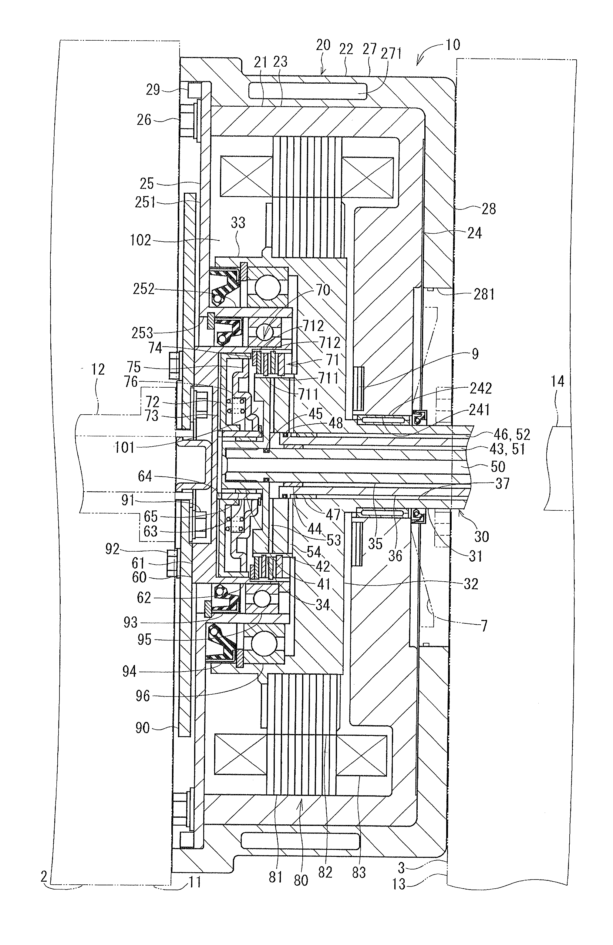
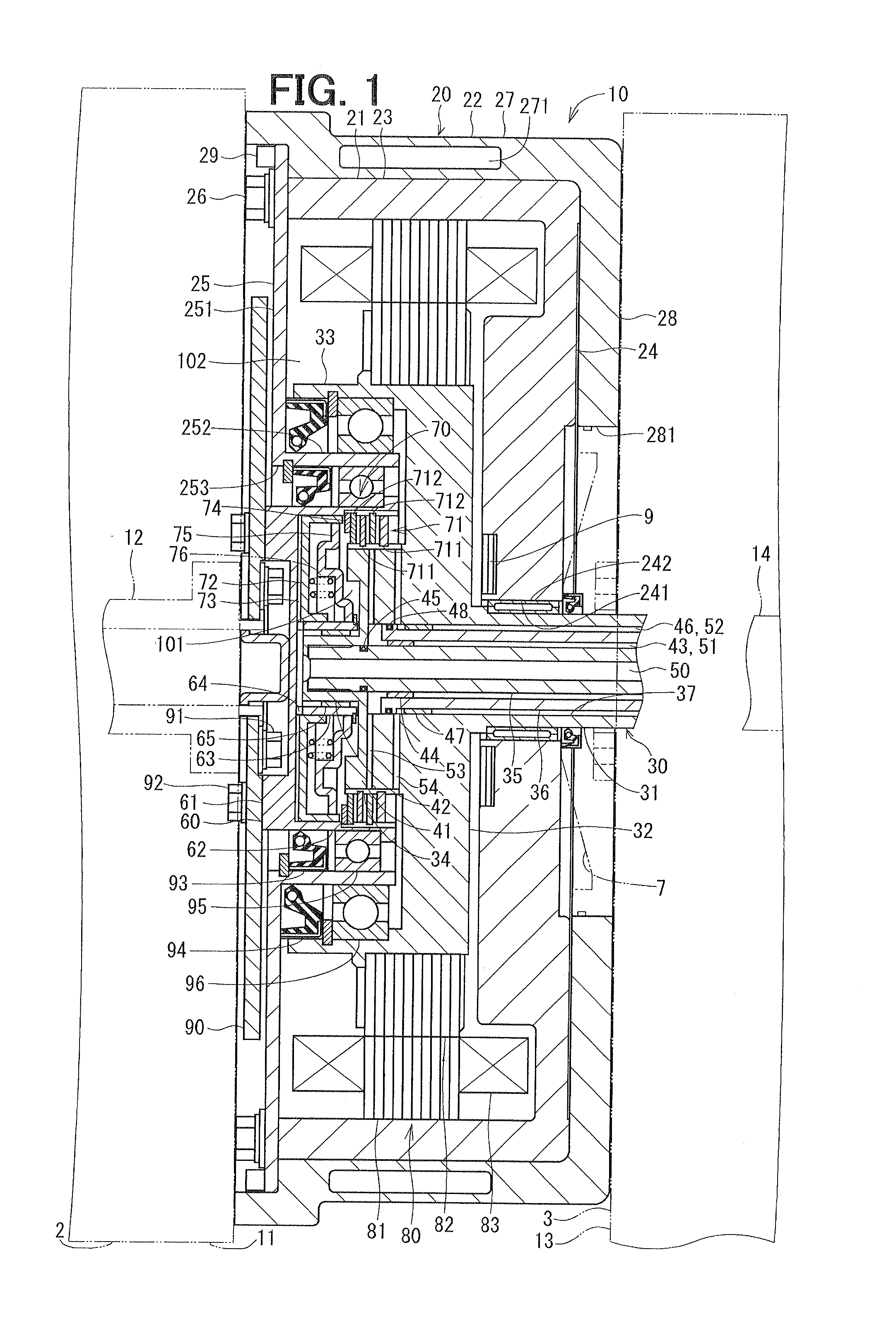
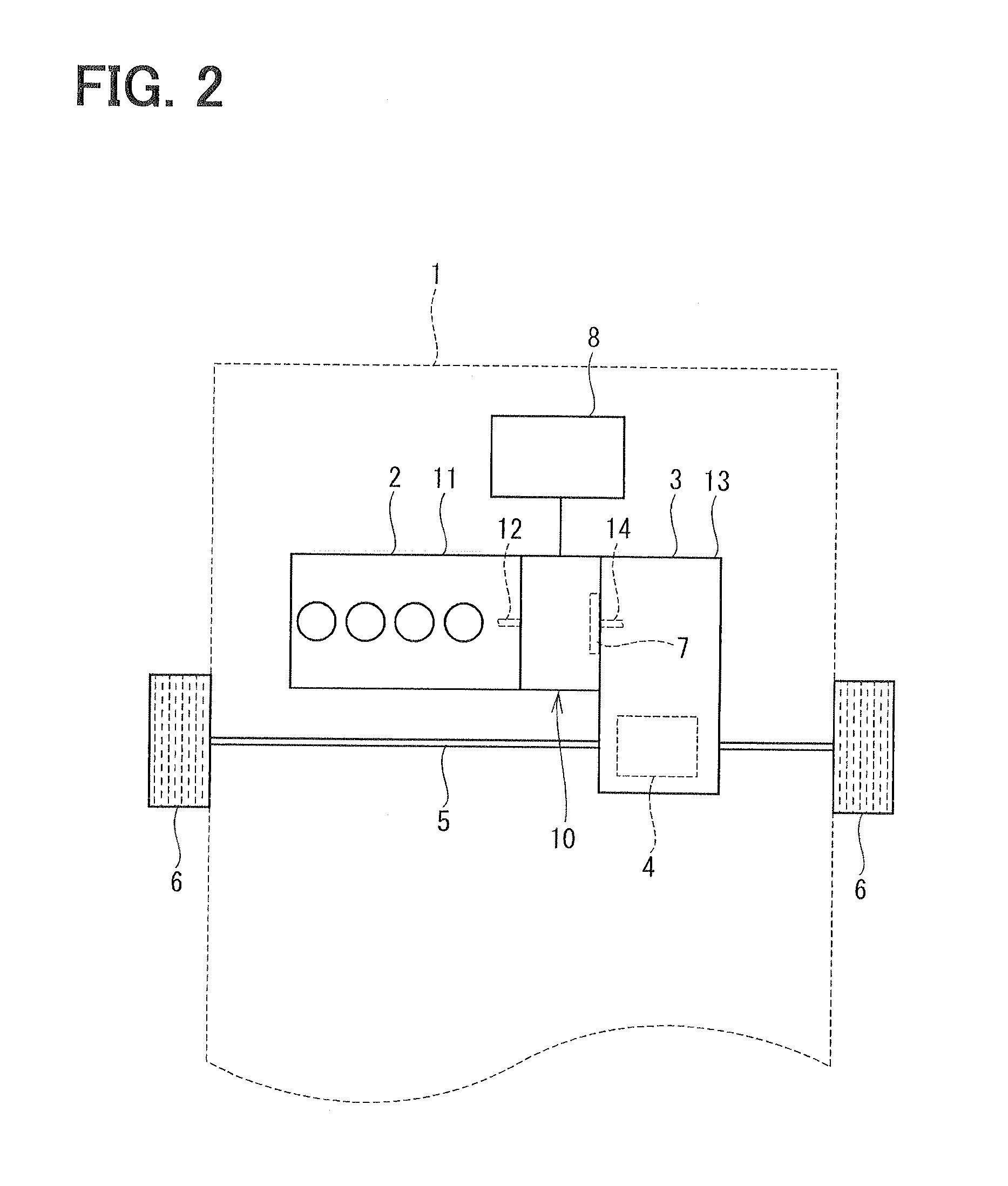
[0028]A power transmitting device of a first embodiment of the present disclosure as well as an example of its application will be explained with reference to FIGS. 1 and 2.

[0029]As shown in FIG. 2, the power transmitting device 10 is arranged between an internal combustion engine 2 of a vehicle 1 and a transmission apparatus 3. The power transmitting device 10 transmits driving force outputted from the engine 2 (operating as a first source for the driving force) to the transmission apparatus 3. The driving force transmitted to the transmission apparatus 3 is further transmitted to an axle 5 via a differential gear 4, wherein speed is decreased or increased by a gear shifting mechanism of the transmission apparatus 3. As a result, vehicle wheels 6 are driven to rotate so that the vehicle 1 travels.

[0030]According to the present embodiment, the engine 2 is mounted on a front side of the vehicle 1 to drive the front wheels 6. In other words, the vehicle 1 is of a front-wheel driven ty...

second embodiment

[0107]A power transmitting device according to a second embodiment is shown in FIG. 3. According to the second embodiment, the shape of the front housing as well as the location of the second bearing member is different from the first embodiment.

[0108]According to the second embodiment, the front housing 25 has a second housing cylindrical portion 254, which is formed in a cylindrical shape and provided at an outer side of the first housing cylindrical portion 252 and which extends from the housing plate portion 251 in the direction opposite to the engine (in the right-hand direction in the drawing), so that an axial forward end of the second cylindrical portion 254 is arranged at a position which is outside of the shaft cylindrical portion 33.

[0109]As in the same manner to the first embodiment, the first bearing member 95 is provided between the outer wall of the drum cylindrical portion 62 and the inner wall of the first housing cylindrical portion 252, so as to rotatably support ...


PUM


Abstract

A main shaft has a shaft cylindrical portion extending from an outer periphery of a large-diameter portion. A drum has a drum cylindrical portion extending from an outer periphery of a drum plate portion. An axial forward end of the drum cylindrical portion is arranged in an inside of the shaft cylindrical portion. A frictional engagement unit of a clutch is provided in an inside of the shaft cylindrical portion. A motor generator has a rotor, which is firmly fitted to outer walls of the large-diameter portion and the shaft cylindrical portion and rotatable relative to a stator. A working-oil supply passage is formed in an inside of an input shaft.

Description

CROSS REFERENCE TO RELATED APPLICATION[0001]This application is based on Japanese Patent Application No. 2011-109445 filed on May 16, 2011, the disclosure of which is incorporated herein by reference.TECHNICAL FIELD[0002]The present disclosure relates to a power transmitting device for transmitting driving force of an engine to a transmission apparatus of a vehicle, in particular to a power transmitting device having a clutch and a motor generator.BACKGROUND[0003]A power transmitting device for a hybrid vehicle is known in the art, according to which a driving force of an engine or a rotational force of a motor generator is operatively transmitted to a transmission apparatus of a vehicle by operating a clutch. According to the power transmitting device, for example, as disclosed in Japanese Patent Publication No. 2006-15997, a frictional engagement unit of a clutch is arranged between an inner wall of a main shaft (which is fitted to a rotor of a motor generator) and an outer wall o...

Claims


Application Information

Patent Timeline
IPC IPC(8): F16D13/38F16D29/00
CPCB60K6/405B60K6/48F16H57/0473Y02T10/6221F16H57/0412F16H57/0476Y02T10/62
Inventor NOGUCHI, HITOSHIOKADA, HIROSHIUSAMI, HIROYUKIYAMASHITA, YOSHIHIRO
Owner DENSO CORP
Learn More