
Dishwasher appliance and a method for operating the same

a technology for dishwashers and washing machines, applied in the direction of cleaning equipment, tableware washing/rinsing machine details, washing and rinsing cycles, etc., can solve the problems of affecting the user's perception of cleanliness and/or appearance, contaminated liquids used during wash and rinse cycles, and inability to leave such particles in wash or rinse fluids

Active Publication Date: 2016-03-17
HAIER US APPLIANCE SOLUTIONS INC
View PDF7 Cites 4 Cited by
  • Summary
  • Abstract
  • Description
  • Claims
  • Application Information

AI Technical Summary

Benefits of technology

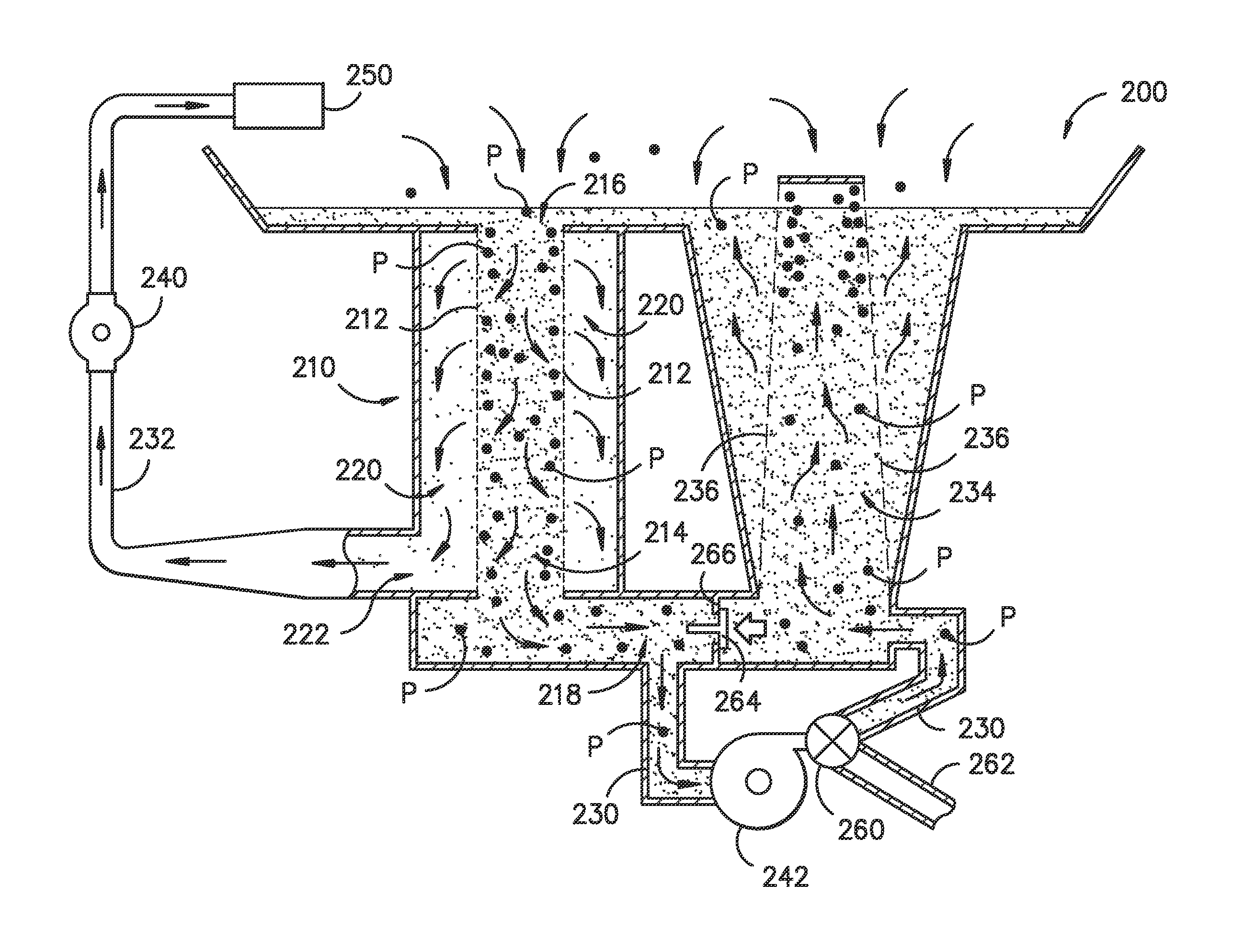
The dishwasher appliance described in this patent has a filter assembly that helps to create a filtered volume, a soil collection volume, and an unfiltered volume in the bottom of the tub. The filter assembly uses a fine filtration filter medium and a coarse filtration filter medium. A spray conduit connects the filtered volume to the spray assembly, while a circulation conduit connects the unfiltered volume to the soil collection chamber. A second pump is connected to the circulation conduit and can direct the wash fluid to either the soil collection chamber or a drain. The technical effect of this design is that it helps to maintain the purity of the wash water during the dishwasher cleaning process.

Problems solved by technology

Depending upon the level of soil on the articles, fluids used during wash and rinse cycles will become contaminated with soils in the form of debris or particles that are carried with the fluid.
However, while some smaller particles may not be harmful to the pump, leaving such particles in the wash or rinse fluid may not be acceptable as these particles may become deposited on the articles being washed / rinsed and thereby affect the user's perception of the cleanliness and / or appearance.
While larger particles can generally be readily removed from the fluid circulated through the wash chamber, challenges are presented in removing smaller particles—particularly as the particle size targeted for removal decreases.
For example, if a dishwashing appliance is provided with a fine particle filter—such as one for removing particles 200 microns or larger—the filter can be prone to clogging particularly during the early stages of the cleaning process.
Unfortunately, this run, drain, and refill approach for unclogging a filter is inefficient as it requires the use of additional fluid (i.e. water).
Of course, a filter media can be selected that only captures larger particles so that it clogs less, such as e.g., 0.030″ or larger, but this comes at the expense of losing the ability to remove smaller particles from the fluid and an associated effect on the resulting cleanliness of the articles.

Method used


Image

  • Dishwasher appliance and a method for operating the same
  • Dishwasher appliance and a method for operating the same
  • Dishwasher appliance and a method for operating the same

Examples


Embodiment Construction

[0018]Reference now will be made in detail to embodiments of the invention, one or more examples of which are illustrated in the drawings. Each example is provided by way of explanation of the invention, not limitation of the invention. In fact, it will be apparent to those skilled in the art that various modifications and variations can be made in the present invention without departing from the scope or spirit of the invention. For instance, features illustrated or described as part of one embodiment can be used with another embodiment to yield a still further embodiment. Thus, it is intended that the present invention covers such modifications and variations as come within the scope of the appended claims and their equivalents.

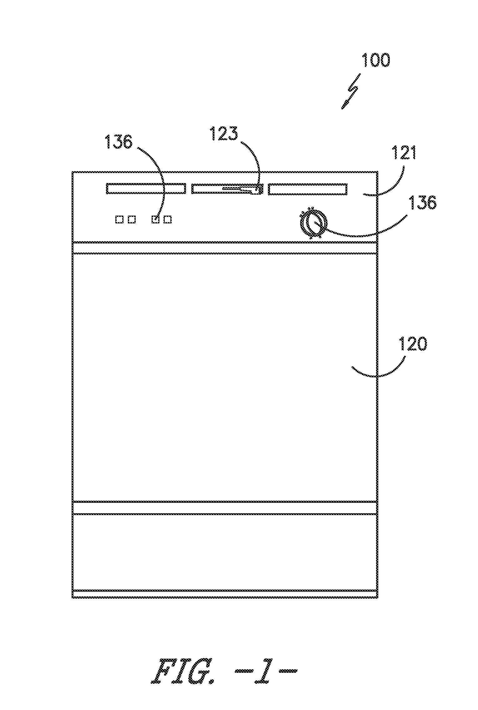
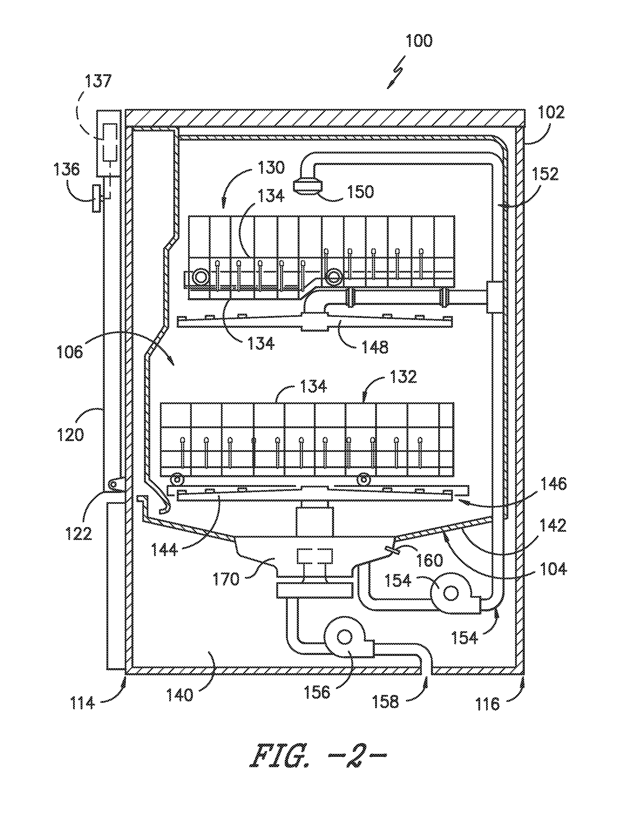
[0019]FIGS. 1 and 2 depict a dishwasher appliance 100 according to an exemplary embodiment of the present subject matter. As shown in FIG. 1, dishwasher appliance 100 includes a cabinet 102. Cabinet 102 has a tub 104 therein that defines a wash chamber or c...


PUM

PropertyMeasurementUnit
sizeaaaaaaaaaa
sizeaaaaaaaaaa
sizeaaaaaaaaaa

Abstract

The present subject matter provides a method for operating a dishwasher appliance. The method includes finely filtering wash fluid with a fine filtration medium via cross-flow filtration and coarsely filtering wash fluid with a coarse filtration medium via dead-end filtration. The finely filtered wash fluid is directed to a spray assembly of the dishwasher appliance. A related dishwasher appliance is also provided.

Description

FIELD OF THE INVENTION[0001]The present subject matter relates generally to dishwasher appliances and methods for operating dishwasher appliances.BACKGROUND OF THE INVENTION[0002]During wash and rinse cycles, dishwasher appliances generally circulate a fluid through a wash chamber over articles, such as pots, pans, silverware, etc. The fluid can be, e.g., various combinations of water and detergent during the wash cycle or water (which may include additives) during the rinse cycle. Typically, the fluid is circulated during a given cycle using a pump. Fluid is collected at or near the bottom of the wash chamber and pumped back into the wash chamber through, e.g., nozzles in spray arms and other openings that direct the fluid against the articles to be cleaned or rinsed.[0003]Depending upon the level of soil on the articles, fluids used during wash and rinse cycles will become contaminated with soils in the form of debris or particles that are carried with the fluid. In order to prote...

Claims


Application Information

Patent Timeline
Patent Type & Authority Applications(United States)
IPC IPC(8): A47L15/42
CPCA47L15/4208A47L15/4225A47L15/4204A47L15/4206A47L2501/03
Inventor THIYAGARAJAN, RAMASAMYMERSCH, MATTHEW DAVIDTARR, RONALD SCOTT
Owner HAIER US APPLIANCE SOLUTIONS INC
Learn More