Access port

Active Publication Date: 2016-03-17
B BRAUN MEDICAL
View PDF6 Cites 0 Cited by
  • Summary
  • Abstract
  • Description
  • Claims
  • Application Information

AI Technical Summary

Benefits of technology

[0022]The at least one extension may be inclined towards or away from the axis of the reservoir. In the preferable case that the extension is inclined towards the axis of the reservoir, it is possible to increase the plastic wall thickness of the wall on the radially inner side of each the extension, in an axial direction from the open end towards the reservoir. Thus the wall strength of the access port is increased at the inner base end. The angle can be chosen so that the extension, in particular the upper end of the extension, avoids interfering with other features of the access port. In order to achieve this, and in the case of more than one extension being provided, the respective angle of each extension may be chosen independently.
[0023]The at least one extension may extend along the entire axial length of the wall. In this way the anchoring of the shielding plate to the housing portion may be further ensured. In a modification of the above-mentioned preferred configuration in which a plurality of extensions, further preferably three extensions, are provided, the extensions may be resiliently laterally deformable and sized so as to be biased against the cylindrical surface of the corepin. As a result, axial alignment of the shielding plate relative to the housing portion is improved since the lateral clearance between the corepin and the extensions is removed. Lateral movement of the shielding plate during the molding process is advantageously reduced. Preferably an orientation of the shielding plate is chosen such that none of the extensions obstructs the exit passage.
[0024]According to an exemplary embodiment, at least one recess is formed on the circular portion laterally beyond at least one extension, pref

Problems solved by technology

The shielding plate can come loose from the housing due to the forces that result from repeated needle insertions and other forces during operation.
In other words the retention of the metallic shielding plate can be compromised which can lead to loss of sealing between the housing and s

Method used


Image

  • Access port
  • Access port
  • Access port

Examples


first embodiment

[0052]A first embodiment of the invention is described in the following.

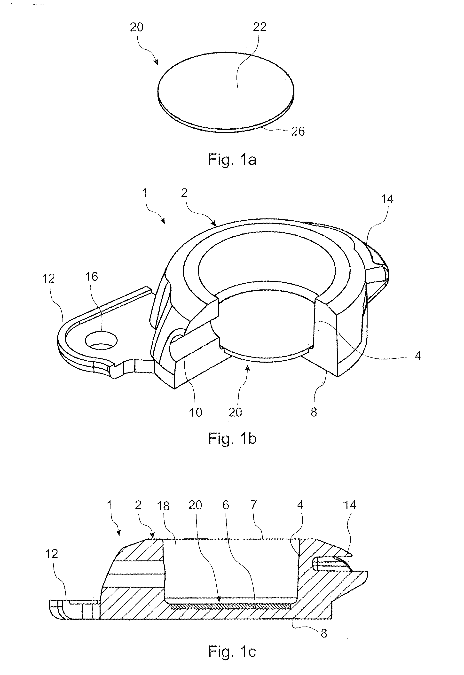
[0053]FIG. 1a is a perspective view of a shielding plate 20. FIG. 1b is a perspective sectional view of a lower housing 2 of an access port 1 (cf. FIG. 6a) comprising the shielding plate 20, wherein the shielding plate 20 is shown unsectioned and the lower housing 2 is shown sectioned. FIG. 1c is a sectional view of the access port 1. The access port 1 has a one-piece lower housing 2 preferably made from molded plastic. A plurality of lugs 12, 14 is integrally formed on the outer surface of the lower housing 2. Preferably the lugs 12, 14 are provided in a triangular arrangement around the lower housing 2, wherein the third lug is not shown in the figures. Suture holes 16 are provided as openings which each extend through a respective lug. The suture holes 16 enable the surgeon, during the implantation procedure, after making an incision in the patient's skin, to fix the lower housing 2 of the access port 1 to th...

second embodiment

[0063]A second embodiment of the invention is described in the following, wherein the differences from the first embodiment are described.

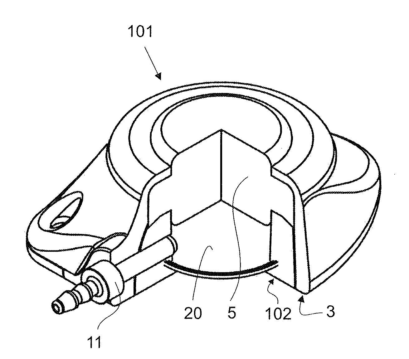
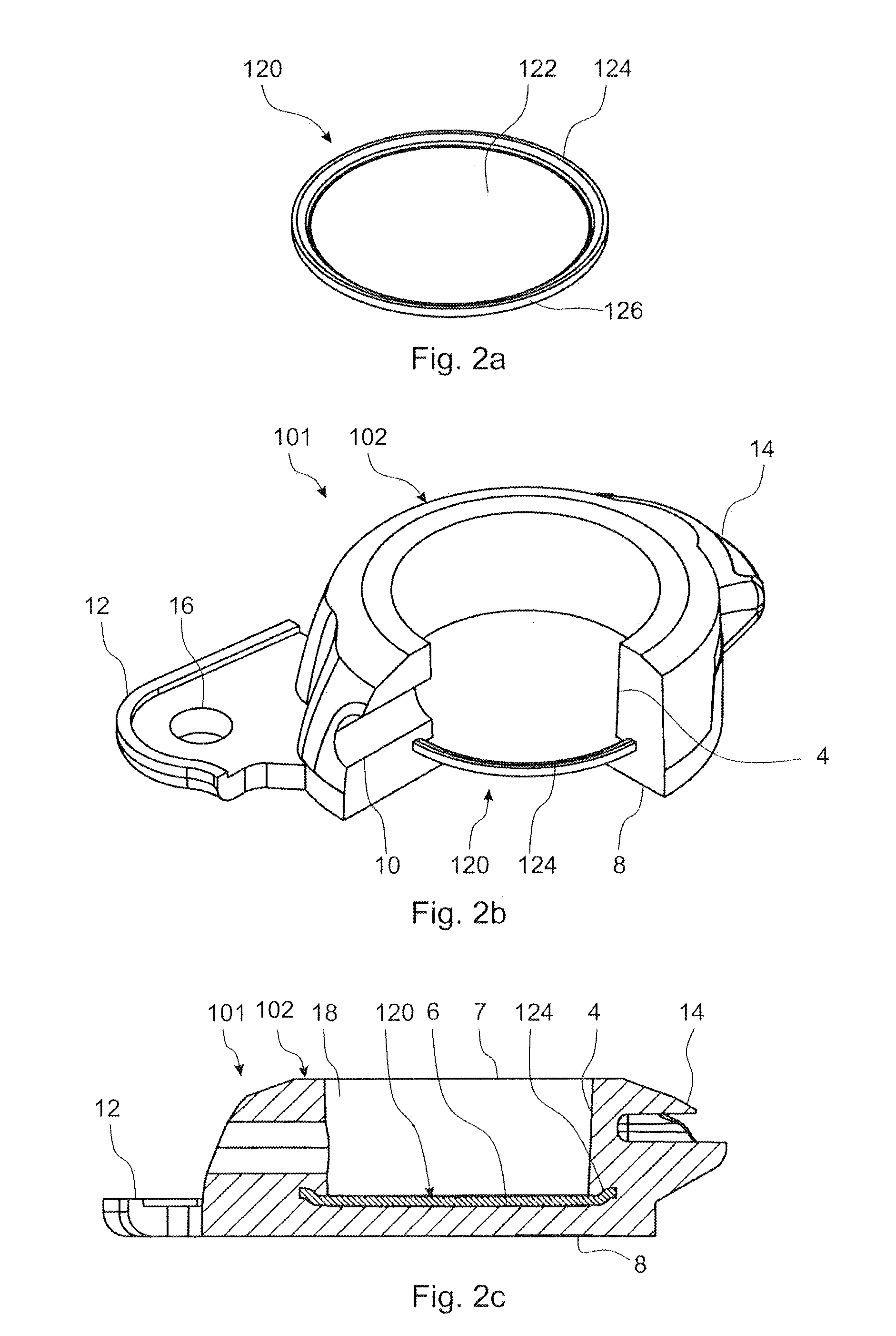
[0064]FIG. 2a is a perspective view of a shielding plate 120. FIG. 2b is a perspective sectional view of a lower housing 102 of an access port 101 comprising the shielding plate 120, wherein the shielding plate 120 is shown unsectioned and the lower housing 102 is shown sectioned. FIG. 2c is a sectional view of the access port 101. As shown most clearly in FIG. 2a, the shielding plate 120 has a bent portion 124 provided all around a circular portion 122, and a periphery 126. As shown most clearly in FIG. 2c, the bent portion 124 extends axially upwards and laterally outwards. Thus a circumferential lip is formed on the shielding plate 120. In the present embodiment the shielding plate 120 has uniform thickness. In the case that the shielding plate 120 is made from metal, it may be cut from sheet or plate and bent to the required shape, for example...

third embodiment

[0079]A third embodiment of the invention is described in the following, wherein the differences from the second embodiment are described.

[0080]FIG. 4a is a perspective view of a shielding plate 220. FIG. 4b is a perspective sectional view of lower housing 202 of an access port 201 comprising the shielding plate 220, with the shielding plate 220 shown unsectioned and lower housing 202 shown sectioned. FIG. 4c is a sectional view of the access port 201. As shown most clearly in FIG. 4a, the shielding plate 220 has a bent portion 224 in the form of three extensions 224 that are arranged on and spaced around the periphery 226 of the circular portion 222.

[0081]As shown in FIGS. 4b to 4c, the shielding plate 220 is integrated with the lower housing 202, preferably by insert molding. As shown most clearly in FIG. 4c, the diameter of the circular portion 222 is greater than the diameter of the wall 4 where the wall 4 meets the inner base 6. In this way an annular region of the upper side o...


PUM

PropertyMeasurementUnit
Diameteraaaaaaaaaa
Lengthaaaaaaaaaa
Metallic bondaaaaaaaaaa

Abstract

An access port includes a molded housing portion forming a reservoir for receiving fluid. The housing portion includes a shielding plate arranged on an inner base of the housing portion; an open end in which a septum is arranged; an exit passage; and a wall, the shielding plate including a circular portion having a periphery. The lower side and the periphery of the shielding plate are embedded into the housing portion. Furthermore, a shielding plate is insert molded into the housing portion.

Description

RELATED APPLICATIONS[0001]This application claims the benefit of priority under 35 U.S.C. §119 of European Application No. EP 14 184 763.2, filed Sep. 15, 2014, the content of which is incorporated herein by reference in its entirety.FIELD OF THE INVENTION[0002]The invention relates generally to an access port, and more particularly to an access port having a housing portion and reservoir for receiving fluid.BACKGROUND[0003]In the administering and / or withdrawal of fluids from a patient, an access port is often used comprising a reservoir having on one end a self-sealing septum through which a needle is insertable. The reservoir further comprises an exit passage fluidly connected to a cannula. After surgically implanting the access port in the patient such that the septum is positioned subcutaneously, and attaching the other end of the cannula to a catheter inserted into an internal part of the body (typically a vein), fluids can be administered and / or blood samples taken through th...

Claims


Application Information

Patent Timeline
IPC IPC(8): A61M39/04A61M39/02B29C45/14
CPCA61M39/0208A61M39/04B29C45/14073B29L2031/753A61M2039/0226A61M2207/00B29K2101/00A61M2039/0205B29C45/17B29C45/26B29C45/2708A61M2039/0202
Inventor BLANLOEIL, PATRICKPRUDHOMME, CYRIL
Owner B BRAUN MEDICAL
Why Eureka
Try Eureka