Application Pen

Active Publication Date: 2016-03-17
SIKA TECH AG
View PDF14 Cites 3 Cited by
  • Summary
  • Abstract
  • Description
  • Claims
  • Application Information

AI Technical Summary

Benefits of technology

[0022]A liquid applicator part (in particular a liquid applicator felt) and/or sponge (absorption sponge) which prevents glass splinters of the ampoule escaping to the outside can be arranged inside the hollow body, as component parts of the application pen.
[0023]The liquid applicator part, in particular t

Problems solved by technology

The prior art proposes breaking devices which require force to be applied in a radial manner (for example as a result of crush

Method used


Image

  • Application Pen
  • Application Pen
  • Application Pen

Examples


Example

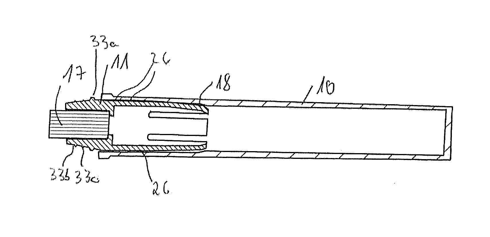
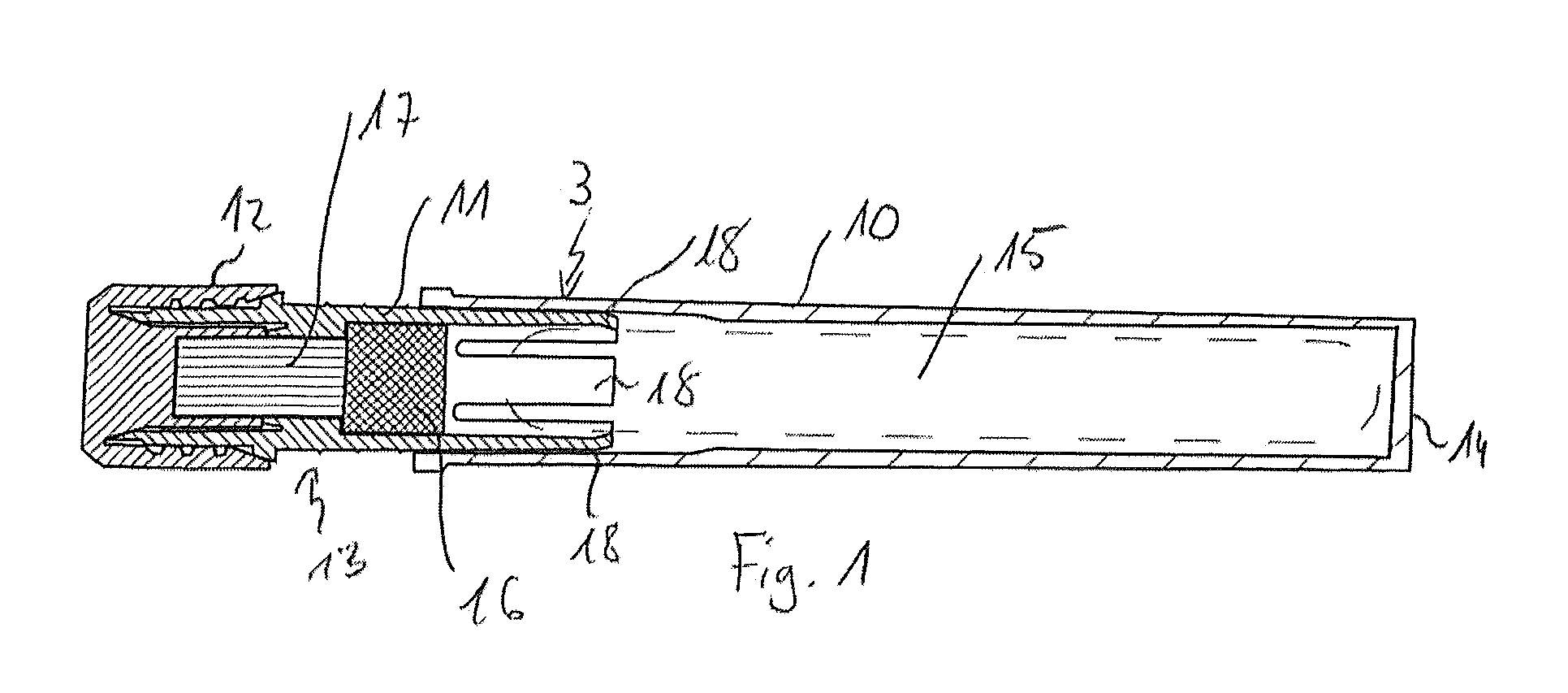
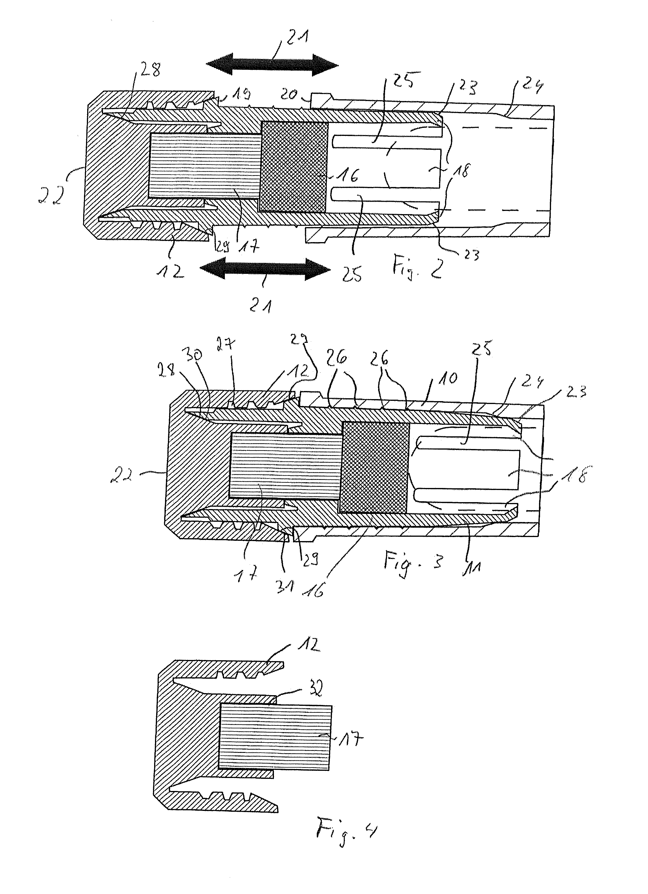
[0044]FIG. 1 shows a schematic section of a first embodiment of an application pen. The application pen includes a base 10, an (axially movable) head part 11 (which realizes a movable portion) and a closure cap 12. The basic body 10, head part 11 and closure cap 12 define a hollow body 3. The basic body 10 comprises an end 14 of the application pen remote from the outlet region 13 (rear end). An ampoule 15 (shown by the broken lines) is arranged in the hollow body 13, specifically inside the basic body 10 and (partially) inside the head part 11. A sponge 16, which prevents the ampoule (or splinters thereof) being able to fall out of the application pen, is additionally provided. The sponge 16 is provided inside the head part 11. A liquid applicator felt 17 is arranged partially inside the head part 11 and the closure cap 12 according to FIG. 1. The ampoule 15 can be broken by means of claws 18 (in the present example four claws are provided but this number is not compulsory) such th...

Example

[0049]FIG. 5 shows a schematic sectional view of a second embodiment of the (in a first position). FIG. 6 shows the embodiment according to FIG. 5 without the closure cap. The ampoule is not shown in FIGS. 5 and 6 for the sake of simplicity, however is arranged in an analogous manner to FIG. 1. The mechanism for breaking the ampoule corresponds to the mechanism according to FIGS. 1 to 4 and is not explained again here. In contrast to the embodiment according to FIGS. 1 to 4, no sponge 16 is provided in the embodiment according to FIGS. 5 to 7. In the embodiment according to FIGS. 5 to 7, the liquid applicator felt 17 prevents the glass splinters being able to escape from the ampoule. To this end, the liquid applicator felt 17 is not integrated in the cap 12 (cf. FIGS. 6 and 7) unlike in the embodiment according to FIGS. 1 to 4, but in the head part 11. Analogous to the embodiment according to FIGS. 1 to 4, the head part 11 is sealed in relation to the basic body 10 by sealing rings ...

Example

[0050]FIG. 8 shows a schematic sectional view of a third embodiment of the application pen. The third embodiment according to FIGS. 8 and 9 corresponds to the first embodiment according to FIGS. 1 to 4 (in particular with regard to the sealing between the head part 11 and the basic body 10 or the head part 11 and the closure cap 12 as well as with regard to the liquid applicator felt 7 and the sponge 16) with the following differences. In the case of the embodiment according to FIGS. 8 and 9, the ampoule 15 is broken by a ring-shaped constriction which provides a predetermined bending point. On account of the ring-shaped constriction 35, the basic body 10 can be bent such that the ampoule 15 breaks. As can be seen in FIG. 9, the liquid applicator felt 17 is arranged inside the closure cap 12 in the case of the third embodiment analogous to FIG. 4.


PUM


Abstract

The invention relates to an application pen for dispensing a liquid onto a surface, such as for applying a protection layer onto adhesion surfaces of a vehicle; for example, for improving adhesion in the case of adhesive applications, the application pen including a hollow body and an ampoule which is received in the hollow body, including a circumferential face, for receiving the liquid, wherein the ampoule can be broken for discharging the liquid, wherein a breaking device with an axially movable portion is provided and is realized in such a manner that a movement of the movable portion in the axial direction results in the breaking of the ampoule.

Description

TECHNICAL SCOPE[0001]The invention relates to an application pen for dispensing a liquid onto a surface, preferably for applying a protection layer onto adhesion surfaces of a vehicle, in particular for improving adhesion in the case of adhesive applications, said application pen including a hollow body, in which the liquid is received, preferably inside an ampoule which is received in the hollow body and can be broken for discharging the liquid.PRIOR ART[0002]Pre-treatment agents for generating adhesive connections are usually provided in packages which consist of an aluminium bottle, polyethylene cup and a screw-type closure of the bottle produced from polyethylene. In the area of single-use applications, aluminium tubes or primer pens and activator pads, in each case with very little contents, are also provided[0003]Application pens of the above-described type are known, for example, from WO 2014 / 004521 A1. WO 2014 / 004521 A1 describes an application pen, including a cylindrical b...

Claims


Application Information

Patent Timeline
IPC IPC(8): B43K8/02
CPCB43K8/024A46B11/0003A46B11/0013B05C17/002B05C17/10
Inventor FEHLMANN, DANIELMAIWALD, DANABURKARD, DOMINIQUE
Owner SIKA TECH AG
Why Eureka
Try Eureka