

Control circuit and method for backlight sources, and image display apparatus and lighting apparatus using the same
- Summary
- Abstract
- Description
- Claims
- Application Information
AI Technical Summary
Benefits of technology
Problems solved by technology
Method used
Image

Examples
Embodiment Construction
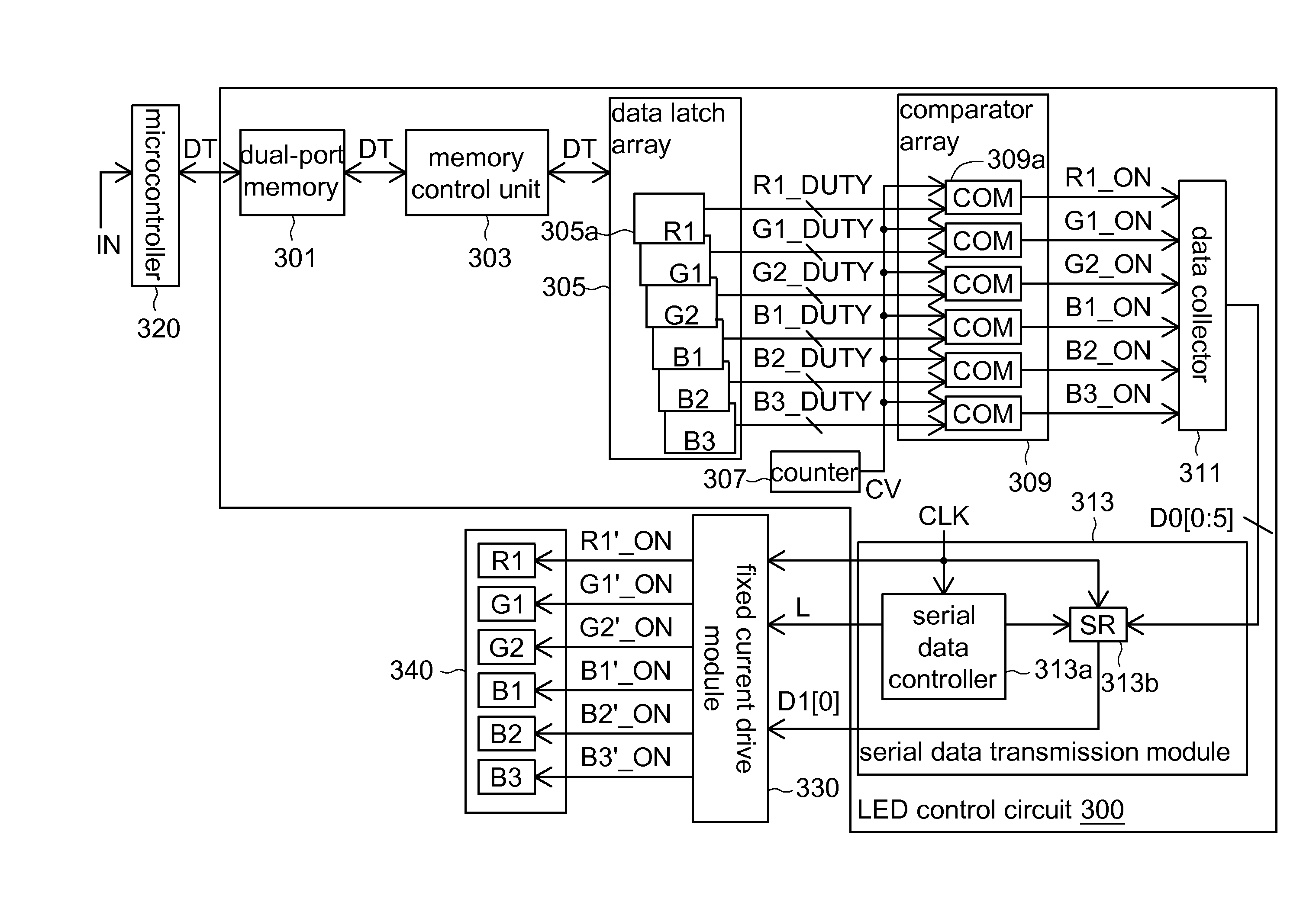
[0036]In embodiments of the invention, the access of data is simplified by way of memory mapping. Besides, the data format is converted, so the number of the I / O pins of the circuit is reduced, and the manufacturing cost is reduced accordingly. Besides, the embodiments of the invention have independent control on brightness of each LED, hence achieving an image display with high contrast and high color saturation.
[0037]An embodiment of the invention provides an LED control circuit used in an image display apparatus or a lighting apparatus having a drive module and a plurality of LEDs. FIG. 3 shows an LED control circuit according to an embodiment of the invention. In the embodiment of the invention, the drive module is a fixed current drive module 330, the LEDs constitute an LED array 340, and the LED control circuit 300 controls each LED of the LED array 340 for light mixture. For convenience of elaboration, the LED array 340 below includes one red light LED R1, two green light LED...
PUM
 Abstract
Description
Claims
Application Information