
Driving force indicator for vehicle

a technology of driving force and indicator, which is applied in the direction of driver input parameters, control devices, instruments, etc., can solve the problem of providing strangeness to the driver, and achieve the effect of suppressing strangeness, and suppressing strangeness to the driver

Inactive Publication Date: 2016-03-17
TOYOTA JIDOSHA KK
View PDF0 Cites 3 Cited by
  • Summary
  • Abstract
  • Description
  • Claims
  • Application Information

AI Technical Summary

Benefits of technology

The invention provides a driving force indicator for a vehicle that reduces the driver's feeling of strangeness by synchronizing the indicated driving force with changes in engine rotation speed or actual driving force. The indicated driving force is changed in response to changes in engine rotation speed or the rotation speed of a predetermined rotating member, which helps to match the driver's experience. This reduces the driver's feeling of strangeness and improves overall driving experience. The electronic control unit can determine the start or end of a change in engine rotation speed or the rotation speed of the predetermined rotating member based on an elapsed time from the time of a shift. This allows for optimal timing of the indicated driving force change without detecting a change in engine rotation speed where necessary. The driving force indicator can also change the engine rotation speed that is indicated during a shift by computing the engine rotation speed separately from the engine rotation speed that is not during the shift and synchronizing the indicated driving force with the change in engine rotation speed during the shift. This reduces the deviation between the indicated engine rotation speed and the indicated driving force, further minimizing the driver's feeling of strangeness.

Problems solved by technology

If the timing of changing the indicated driving forces is inappropriate, there occurs a deviation between changes in indicated driving forces and a change in engine rotation speed on a tachometer or a change in actual driving force, so there is a possibility that a feeling of strangeness is provided to the driver.

Method used


Image

  • Driving force indicator for vehicle
  • Driving force indicator for vehicle
  • Driving force indicator for vehicle

Examples


Embodiment Construction

[0019]Hereinafter, an embodiment of the invention will be described in detail with reference to the accompanying drawings. In the following embodiment, the drawings are modified or simplified where appropriate, and the scale ratio, shape, and the like, of each portion are not always drawn accurately.

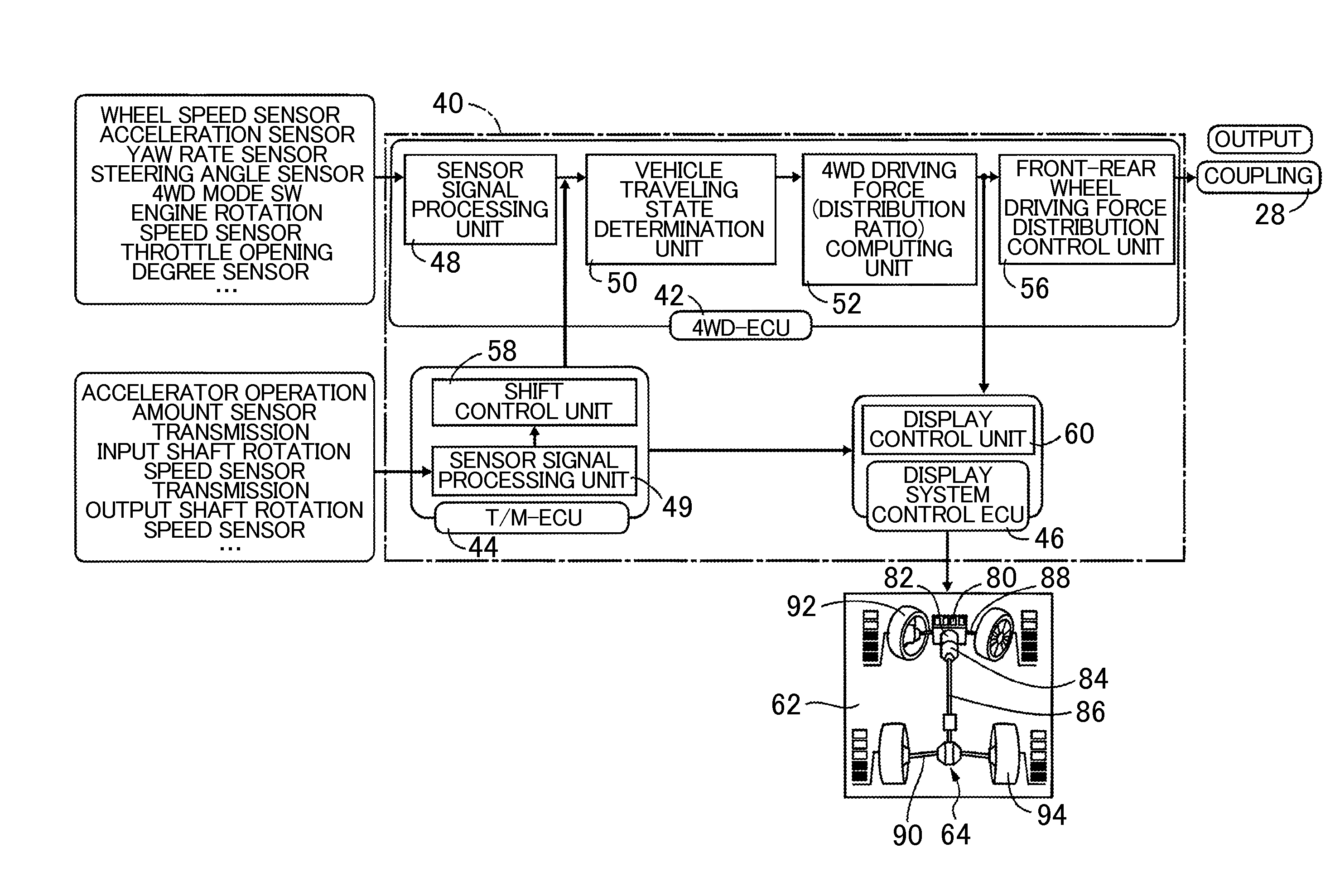
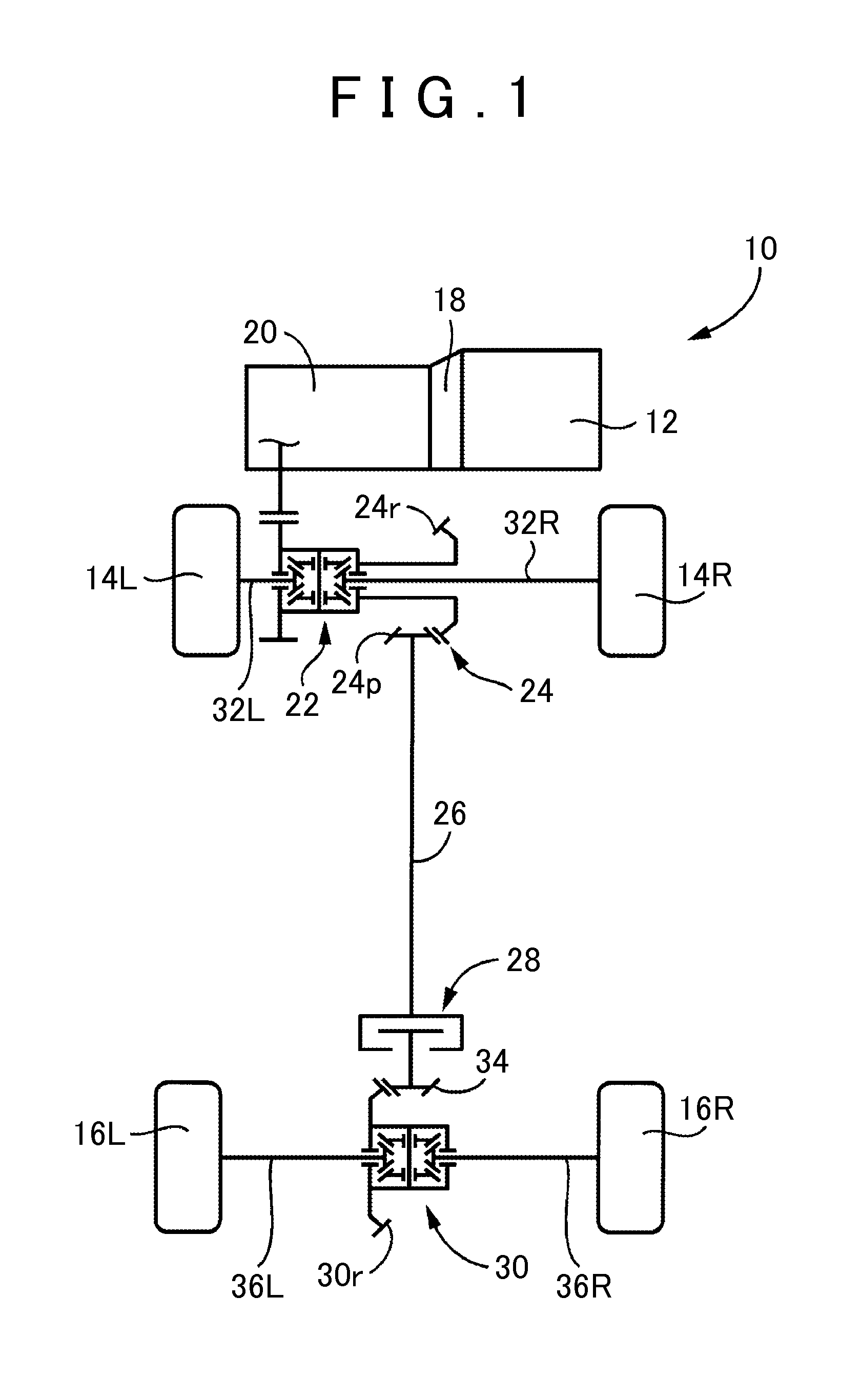
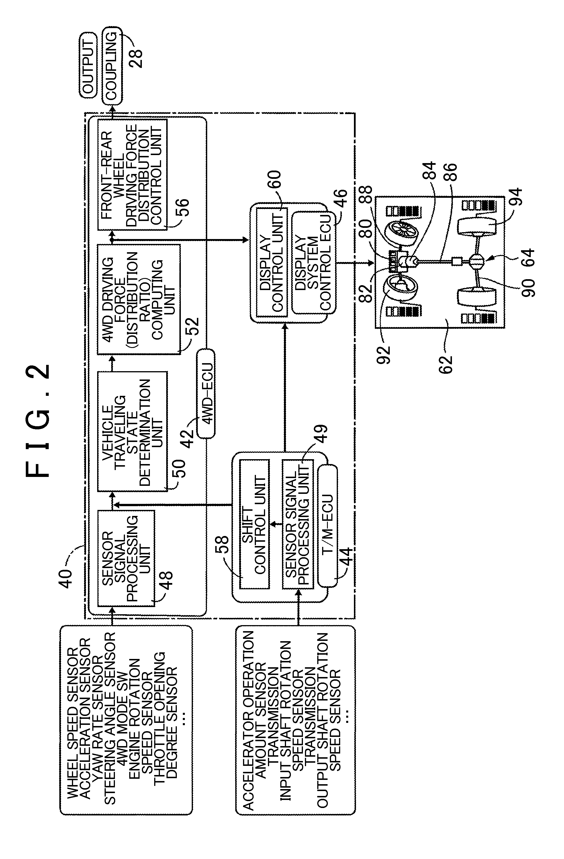
[0020]FIG. 1 is a skeletal view that illustrates the outline of a driving system 10 for a vehicle, to which a driving force indicator for a vehicle is applied, according to the embodiment of the invention. In FIG. 1, the driving system 10 is an FF-base four-wheel drive system that uses an engine 12 as a driving source. The FF-base four-wheel drive system includes two power transmission paths. One of the power transmission paths transmits the power of the engine 12 to front wheels 14R, 14L (when not particularly distinguished from each other, referred to as front wheels 14). The other one of the power transmission paths transmits the power of the engine 12 to rear wheels 16R, 16L (when no...


PUM


Abstract

A driving force indicator for a vehicle is provided. The vehicle includes a transmission. The driving force indicator includes a display and at least one electronic control unit. The electronic control unit is configured to control the display such that at least a driving force of a front wheel or rear wheel of the vehicle is indicated on the display. The electronic control unit is configured to change the driving force indicated on the display in synchronization with a change in driving force of the vehicle, a change in engine rotation speed or a change in rotation speed of a predetermined rotating member, caused by shift control over the transmission. The predetermined rotating member is a component of the transmission.

Description

INCORPORATION BY REFERENCE[0001]The disclosure of Japanese Patent Application No. 2014-189371 filed on Sep. 17, 2014 including the specification, drawings and abstract is incorporated herein by reference in its entirety.BACKGROUND OF THE INVENTION[0002]1. Field of the Invention[0003]The invention relates to a driving force indicator for a vehicle and, more particularly, to optimization of the timing of changing an indicated driving force during a shift.[0004]2. Description of Related Art[0005]In a four-wheel drive vehicle, or the like, there is suggested a system that shows a vehicle model (vehicle model image) on an in-vehicle display provided at a driver seat, or the like, and that indicates the driving force of each wheel beside a corresponding one of wheels of the vehicle model image. A torque indicator for a vehicle, described in Japanese Patent Application Publication No. 2011-46362 (JP 2011-46362 A), is one example of the system. The torque indicator for a vehicle, described ...

Claims


Application Information

Patent Timeline
Patent Type & Authority Applications(United States)
IPC IPC(8): B60W50/08B60W10/06B60W10/10B60W30/18B60W30/19B60W50/14
CPCB60W50/085B60W30/18009B60W30/19B60W10/10B60W2710/1005B60W50/14B60W2050/146B60W2710/0644B60W10/06B60W2510/0652B60W2520/30B60W2520/403B60W2520/406B60W2540/165
Inventor SHIMIZU, SATOSHIIWATSUKI, KUNIHIRO
Owner TOYOTA JIDOSHA KK
Learn More