Micro-gas pressure driving device

a micro-gas and pressure driving technology, applied in the direction of pump components, positive displacement liquid engines, liquid fuel engine components, etc., can solve the problems of bulky volume of pressure driving devices or pressure driving machines, inconvenient portability, and failure to meet the miniaturization requirements of conventional pressure driving devices

Active Publication Date: 2016-03-17
MICROJET TECH
View PDF11 Cites 118 Cited by
  • Summary
  • Abstract
  • Description
  • Claims
  • Application Information

AI Technical Summary

Problems solved by technology

However, due to the volume limitations of the motors and the pressure valves, the pressure driving devices or the pressure driving machines are bulky in volume.
In other words, the conventional pressure driving device fails to meet the miniaturization requirement and is not portable.
Moreover, during operations of the motor or the pressure valve, annoying noise is readily generated.
That is, the conventional pressure driving device is neither friendly nor comfortable to the user.

Method used


Image

  • Micro-gas pressure driving device
  • Micro-gas pressure driving device
  • Micro-gas pressure driving device

Examples


Embodiment Construction

[0021]The present invention will now be described more specifically with reference to the following embodiments. It is to be noted that the following descriptions of preferred embodiments of this invention are presented herein for purpose of illustration and description only. It is not intended to be exhaustive or to be limited to the precise form disclosed.

[0022]The present invention provides a micro-gas pressure driving device. The micro-gas pressure driving device may be used in many sectors such as pharmaceutical industries, energy industries, computer techniques or printing industries for transporting gases.

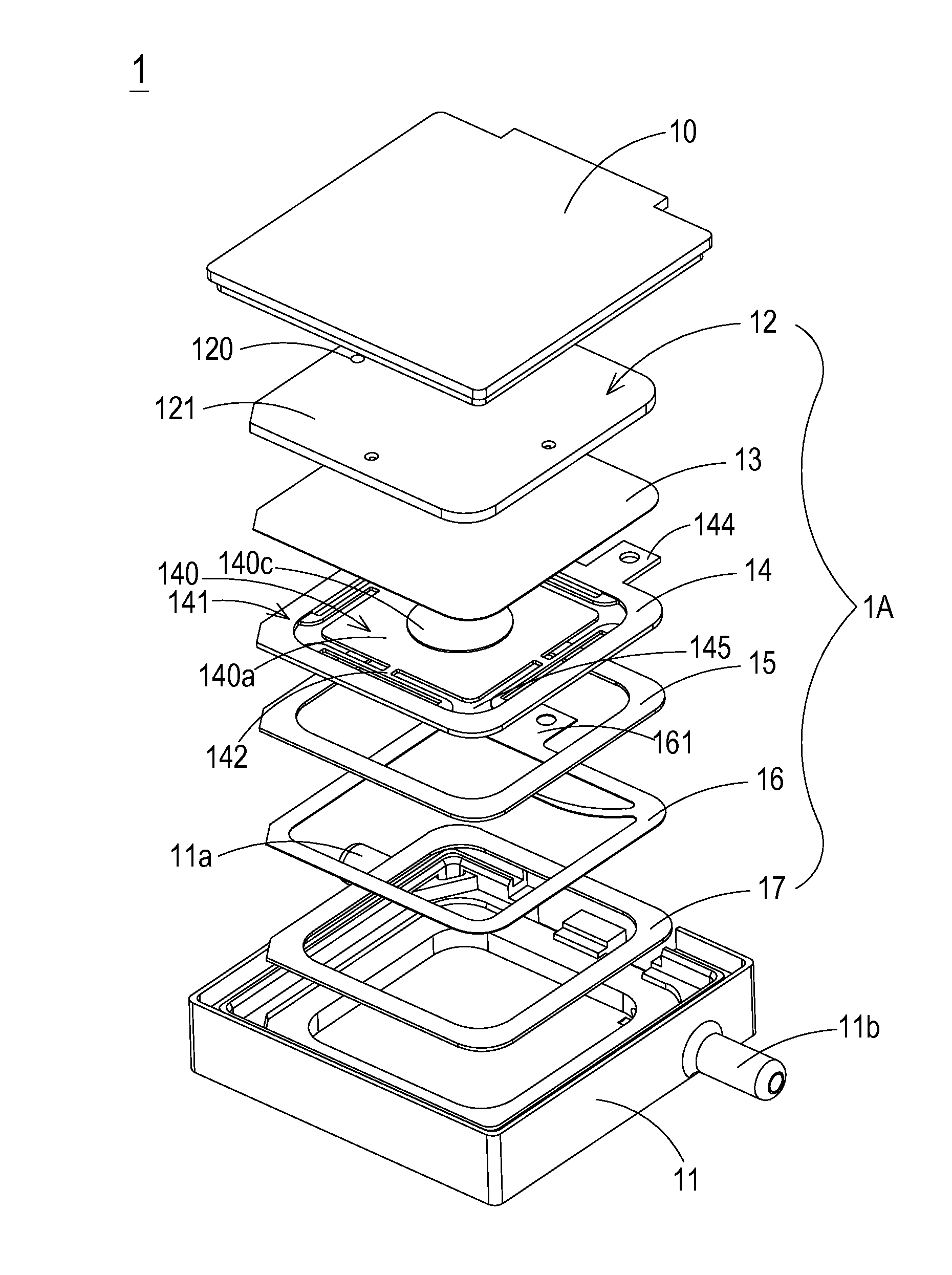
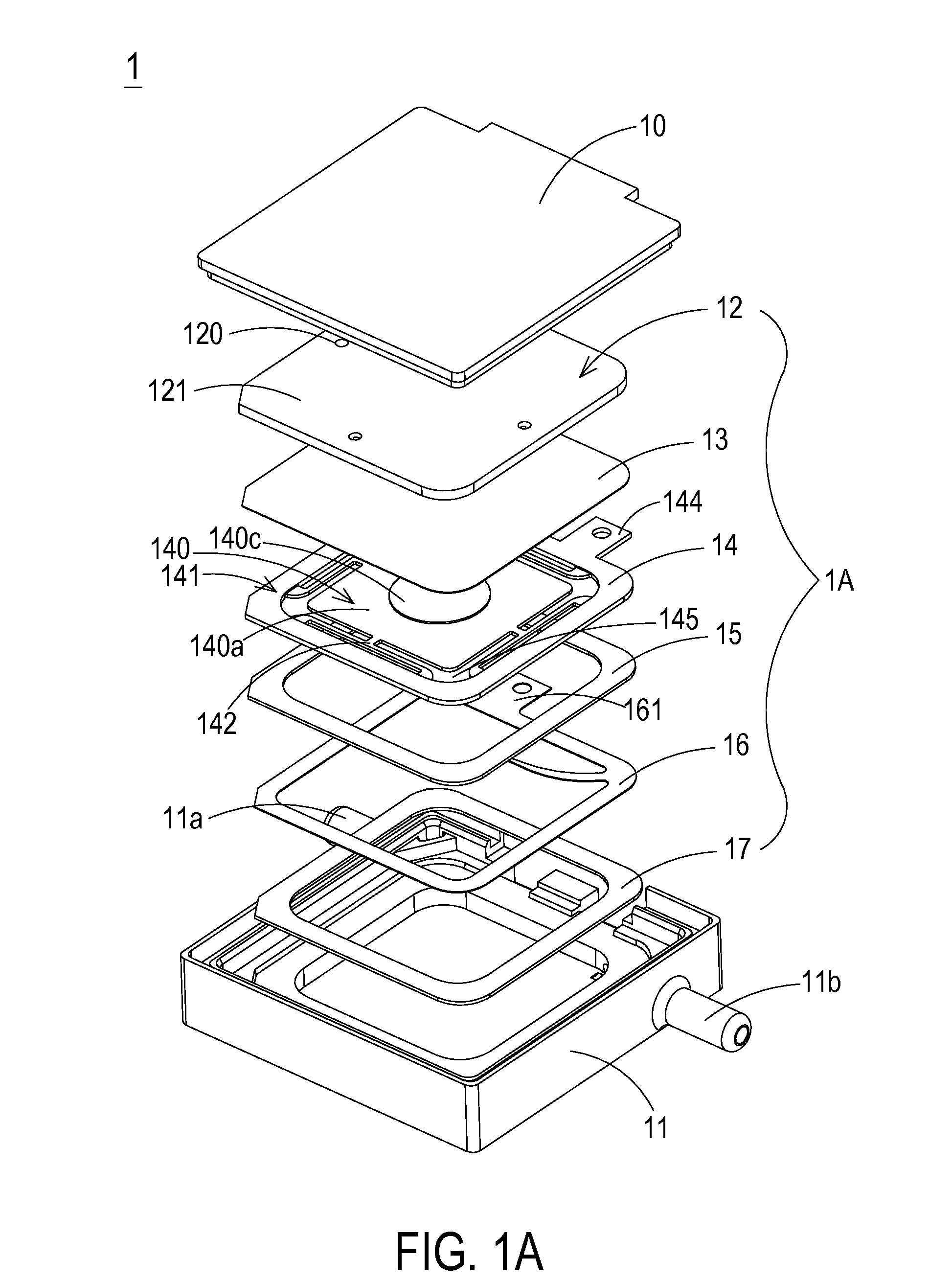
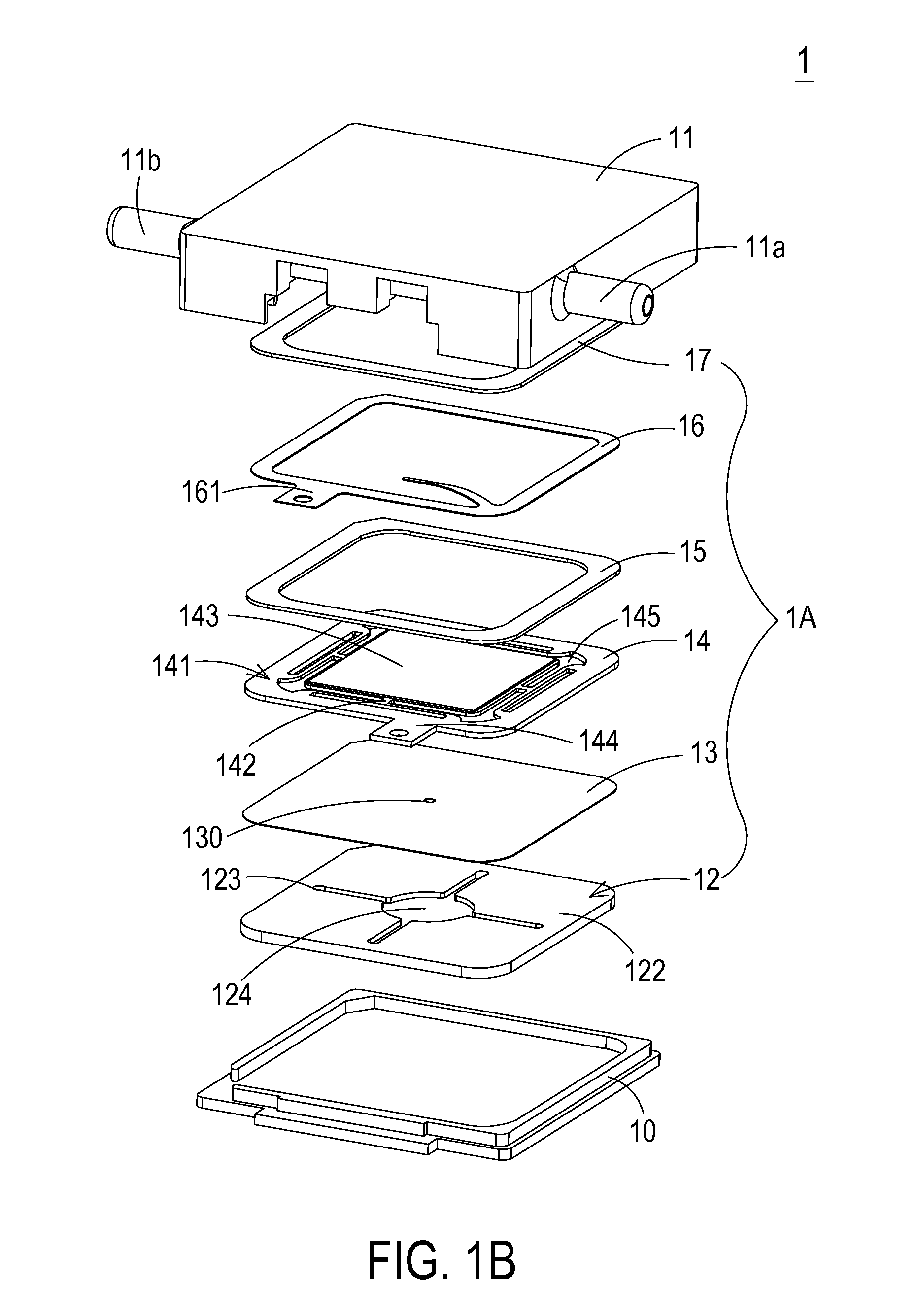
[0023]FIG. 1A is a schematic exploded view illustrating a micro-gas pressure driving device according to a first embodiment of the present invention and taken along a front side. FIG. 1B is a schematic exploded view illustrating the micro-gas pressure driving device according to the first embodiment of the present invention and taken along a rear side. As shown in FIGS. 1A a...


PUM


Abstract

A micro-gas pressure driving device includes a miniature gas transportation module, a covering plate and a tube plate. The miniature gas transportation module includes a convergence plate, a resonance membrane and a piezoelectric actuator. When the piezoelectric actuator is activated to feed a gas into an input tube of the tube plate, the gas is sequentially transferred through a first input chamber, a second input chamber, an inlet, a convergence channel and a central opening of the convergence plate, a central aperture of the resonance membrane, and transferred downwardly through the piezoelectric actuator and an output chamber, and outputted from an output tube of the tube plate. The first input chamber is arranged between the covering plate and the input tube. The second input chamber is defined between the covering plate and the convergence plate. The output chamber is defined between the tube plate and the piezoelectric actuator.

Description

FIELD OF THE INVENTION[0001]The present invention relates to a pressure driving device, and more particularly to a slim and silent micro-gas pressure driving device.BACKGROUND OF THE INVENTION[0002]With the advancement of science and technology, fluid transportation devices used in many sectors such as pharmaceutical industries, computer techniques, printing industries or energy industries are developed toward elaboration and miniaturization. The fluid transportation devices are important components that are used in for example micro pumps, micro atomizers, printheads or industrial printers. Therefore, it is important to provide an improved structure of the fluid transportation device.[0003]For example, in the pharmaceutical industries, pressure driving devices or pressure driving machines use motors or pressure valves to transfer gases. However, due to the volume limitations of the motors and the pressure valves, the pressure driving devices or the pressure driving machines are bul...

Claims


Application Information

Patent Timeline
Patent Type & Authority Applications(United States)
IPC IPC(8): F04B43/04F04B53/16
CPCF04B53/16F04B43/046F04B45/047
Inventor CHEN, SHIH-CHANGLIAO, JIA-YUKUO, CHENG-TSE
Owner MICROJET TECH
Why Eureka
Try Eureka