Operation device

a technology of operation device and operation feeling, which is applied in the direction of static indicating device, transformer/inductance magnetic core, instruments, etc., can solve the problems of further deterioration of operation feeling when an operator operates the operation unit, and achieves enhanced operation feeling when an operator operates the operation portion , the effect of large frictional for

Inactive Publication Date:
View PDF2 Cites 9 Cited by
  • Summary
  • Abstract
  • Description
  • Claims
  • Application Information

AI Technical Summary

Benefits of technology

[0009]In the operation device configured as above, the coil-side yoke is disposed to the coil on the opposite side of the magnet. In short, the coil is disposed between the coil-side yoke and the magnet. Nevertheless, the coil-side yoke is held by the mobile body so as to move with the magnet. Hence, the configuration as above can avoid an inconvenience that a magnetic attraction force acting between the coil-side yoke and the magnet is exerted over the holding body and the mobile body. In short, an inconvenience that the mobile body is pressed against the holding body by the magnetic attraction force can be avoided. Hence, the configuration as above can avoid an inconvenience that a large frictional force is generated between the mobile body and the holding body when the mobile body in contact with the holding body moves relatively with respect to the holding body. Consequently, an operation feeling when an operator operates the operation portion is enhanced.

Problems solved by technology

An operation feeling when an operator operates the operation unit is thus deteriorated.
The operation feeling is thus further deteriorated.

Method used


Image

  • Operation device
  • Operation device
  • Operation device

Examples


first embodiment

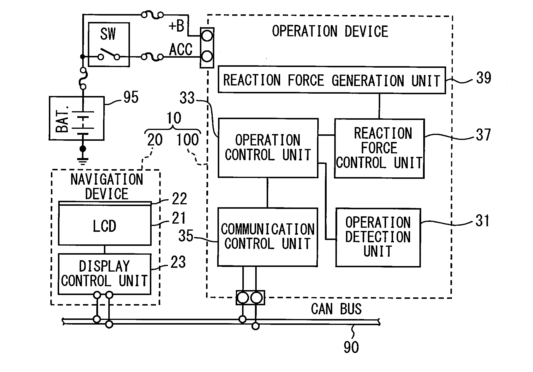
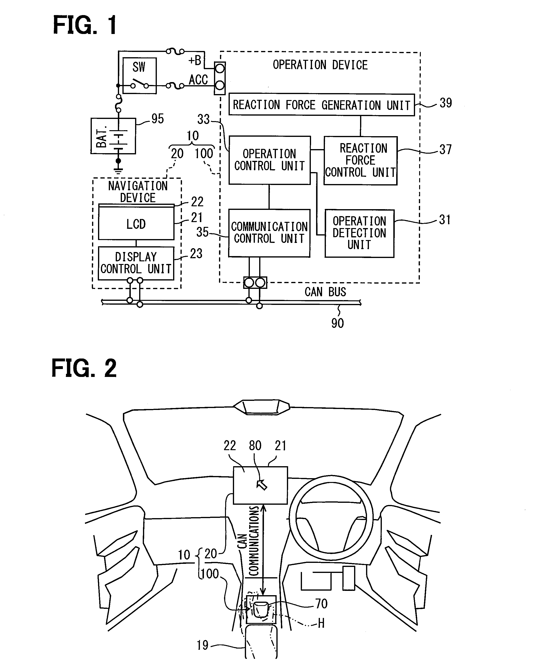
[0017]An operation device 100 of the present embodiment is mounted to a vehicle and, as is shown in FIG. 1, forms a display system 10 together with a navigation device 20 and so on. As is shown in FIG. 2, the operation device 100 is disposed to a vehicle center console at a position next to a palm rest 19, and an operation knob 70 is exposed in a range easy to reach for a hand H of an operator. Upon input of an operation force by the hand H of the operator or the like, the operation knob 70 undergoes displacement in a direction of the input operation force. The navigation device 20 is disposed within a vehicle instrument panel and a display screen 22 is exposed toward a driver's seat. The display screen 22 displays multiple icons correlated with respective predetermined functions, a pointer 80 used to choose an arbitrary icon, and so on. Upon input of a horizontal operation force to the operation knob 70, the pointer 80 moves on the display screen 22 in a direction corresponding to ...

second embodiment

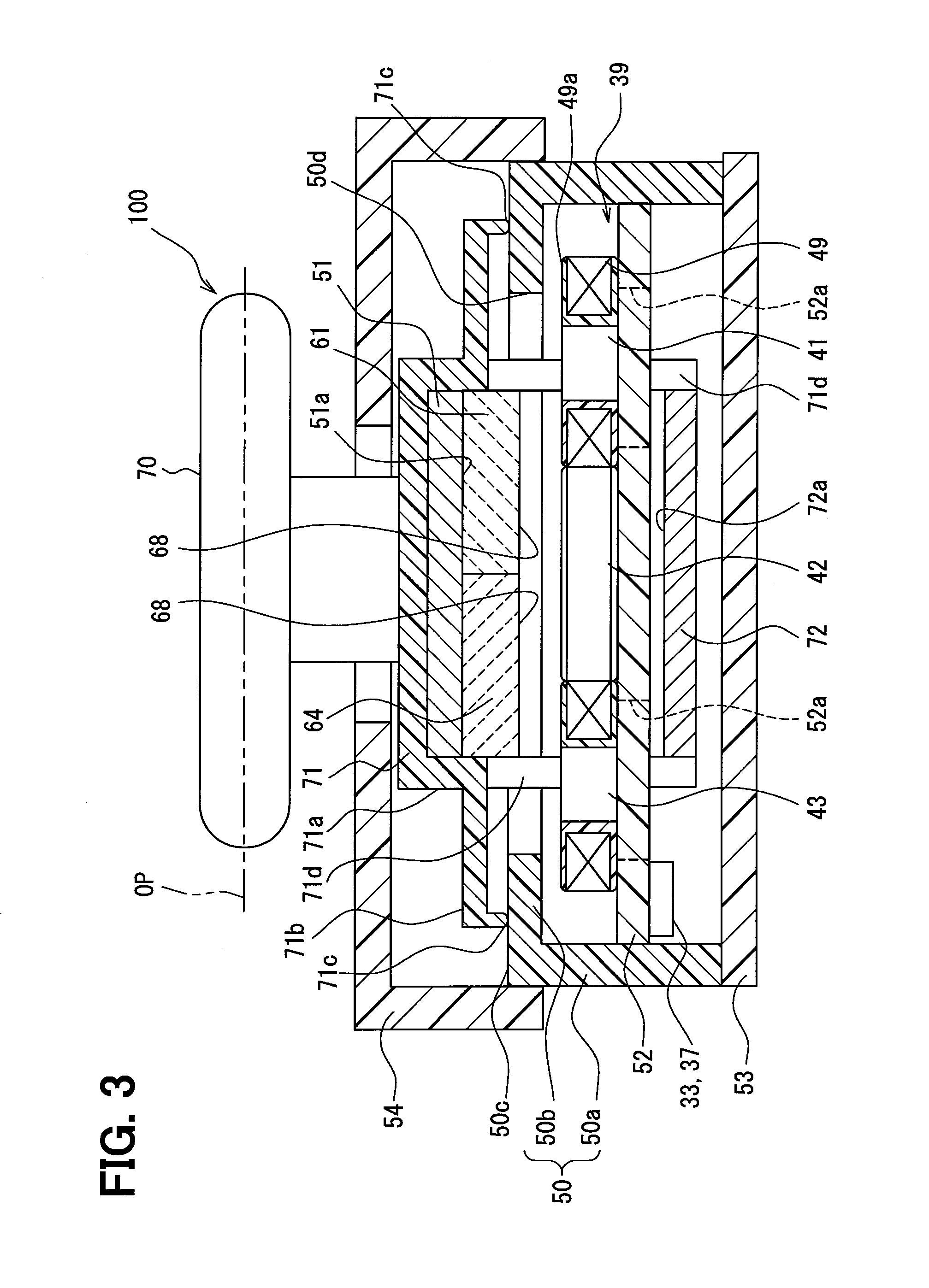
[0066]In contrast to the operation device 100 of the first embodiment above in which the outer edges of the coil-side yoke 72 is held by the brackets 71d, a center portion of a coil-side yoke 72 is held by a bracket 71e in an operation device 100A of the present embodiment as shown in FIG. 6.

[0067]The bracket 71e is positioned at a center of a combination magnet and disposed so as to penetrate through openings 50d and 52b provided to a housing 50 and a circuit board 52, respectively. One end of the bracket 71e is attached to a knob base 71 or magnets 61 through 64 and the other end of the bracket 71e is attached to the coil-side yoke 72.

Other Embodiments

[0068]While the preferred embodiments of the disclosure have been described, it should be appreciated that the disclosure is not limited to the embodiments described above and can be implemented in various modifications. For example, the both yokes 51 and 72 are shaped like a flat plate having no irregularities in the first embodimen...


PUM


Abstract

An operation device includes: a magnet; a coil; an operation unit; a holding body; a mobile body; and a coil-side yoke. The holding body holds the coil. The mobile body holds the magnet so as to provide a predetermined clearance between the coil and the magnet. The mobile body is in contact with the holding body and movable relatively with respect to the holding body due to the operation force input into the operation unit. The coil-side yoke is disposed on the coil opposite to the magnet so as to lead the magnetic line generated by the magnet to the coil. The coil-side yoke is held by the mobile body so as to be movable with the magnet.

Description

CROSS REFERENCE TO RELATED APPLICATION[0001]This application is based on Japanese Patent Application No. 2013-97853 filed on May 7, 2013, the disclosure of which is incorporated herein by reference.TECHNICAL FIELD[0002]The present disclosure relates to an operation device in which an operation force is input.BACKGROUND ART[0003]Patent literature 1 discloses an operation device configured to enable an operator to feel a reaction force of operation by conferring an actuating force generated in an actuator to an operation unit in which to input an operation force. The actuator has coils held by a holding body and magnets held by a mobile body. Upon input of an operation force to the operation unit, the mobile body in contact with the holding body moves relatively with respect to the holding body while maintaining the coils and the magnets spaced apart by a constant distance. An electromagnetic force generated when a current is passed through the coils is exerted on the operation unit a...

Claims


Application Information

Patent Timeline
Patent Type & Authority Applications(United States)
IPC IPC(8): G06F3/01G06F3/0354G06F3/038H01F27/24H01F27/28
CPCG06F3/016G06F3/0354H01F27/2823H01F27/24G06F3/038B60K37/06B60K2370/126B60K2370/128B60K2370/133H02K41/0356
Inventor TACHIIRI, MOTOKI
Why Eureka
Try Eureka