

Lubricator
- Summary
- Abstract
- Description
- Claims
- Application Information
AI Technical Summary
Benefits of technology
Problems solved by technology
Method used
Image

Examples
Example
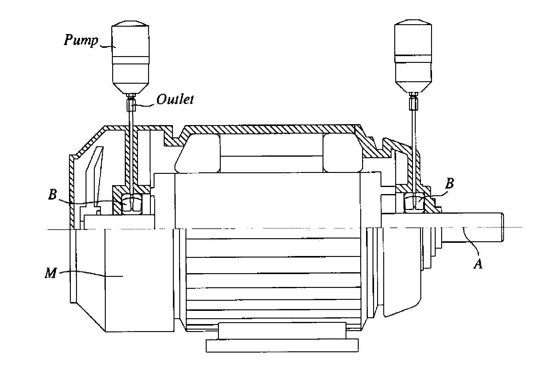
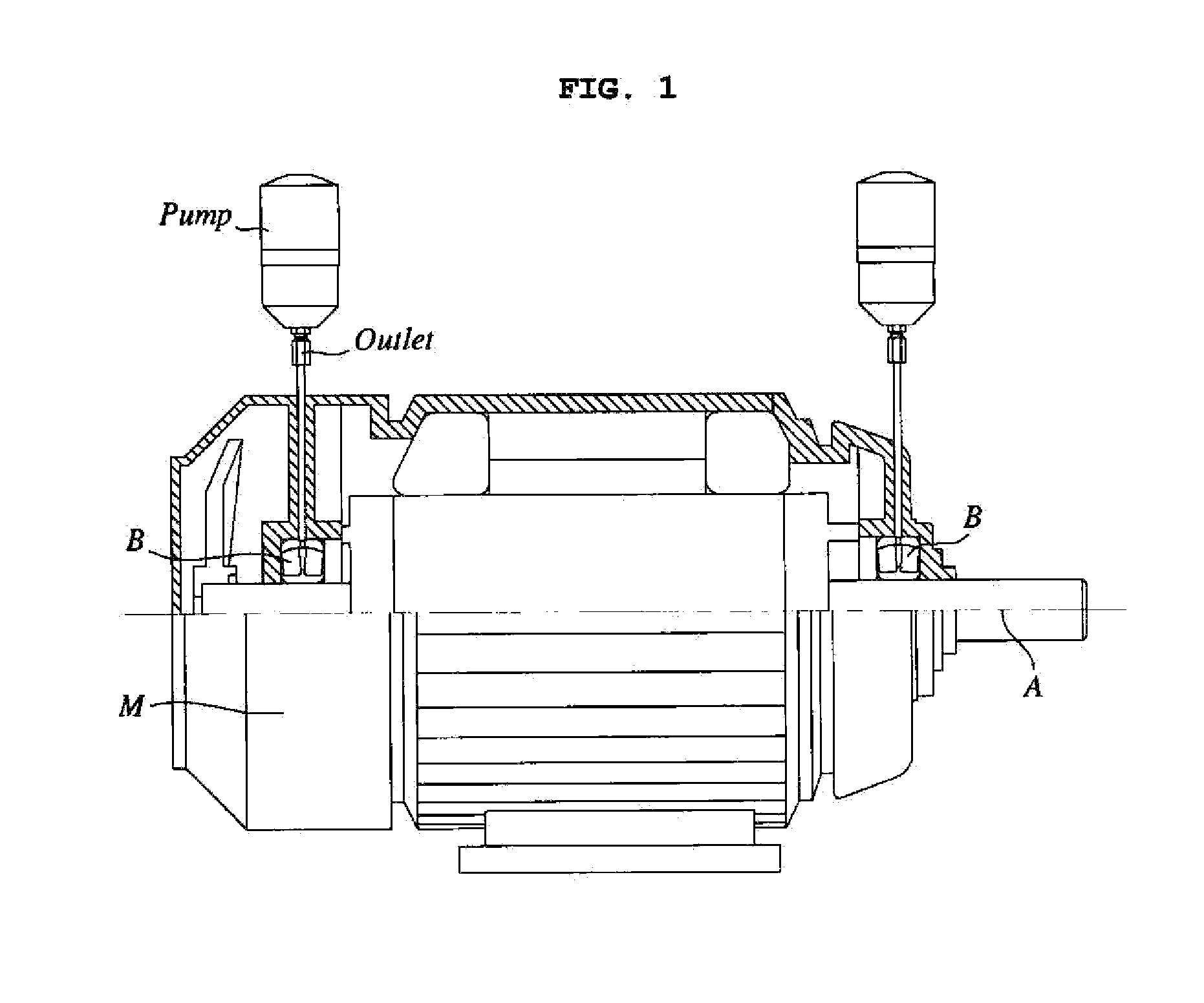
[0004]However, a typical rotating machine, such as a motor M shown in FIG. 1, has two lubrication target points because both ends of a rotating shaft A are supported by respective bearings B. Accordingly, in the case of the conventional art, two lubrication pumps are generally applied to the single rotating machine M, as shown in FIG. 1. In other words, the conventional art has problems including inefficiency and higher cost because two lubrication pumps are required to lubricate a rotating machine.
[0005]In another conventional art that uses a lubrication pump and also a special valve, such as a distributing valve, can make lubricant discharged from one single outlet of the lubrication pump be separately discharged to two outlets through the distributing valve. However, since the distribution valve is added to the single pump, this technology also has problems in that installation is complicated and costs are increased.
[0006]In still another conventional art, a passage can be divide...
PUM
 Abstract
Description
Claims
Application Information