
Panel with reduced glare

a panel and glare technology, applied in the field of panels with reduced glare, can solve the problems of large spectrum of light, low reflectivity of darkly colored panels, and limited colors that may be offered, and achieve the effect of reducing the glare of the veil

Active Publication Date: 2016-03-24
RGT UNIV OF MICHIGAN +1
View PDF9 Cites 12 Cited by
  • Summary
  • Abstract
  • Description
  • Claims
  • Application Information

AI Technical Summary

Benefits of technology

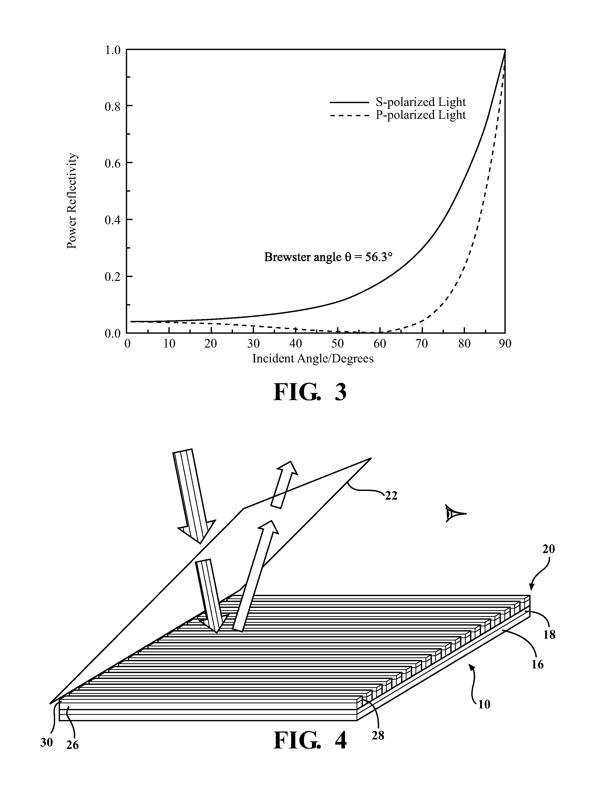
The patent describes a panel that reduces glare while maintaining the color of a window. The panel includes a wire-grid polarizer (WGP) that reflects certain light and transmits other light. The WGP has a metallic grid with narrow passages that reflect P-polarized light and allow S-polarized light to pass through. The panel also includes a thin film layer that modifies the reflectivity spectrum of the WGP to reflect a predetermined spectrum of light. The thin film layer can be a lossy dielectric such as a semiconductor. The technical effect of this invention is to provide a glare-reducing panel with a dynamic reflectivity spectrum that maintains the brightness of the panel's color.

Problems solved by technology

It is known that darkly colored panels have low-reflectivity, but also absorbed a larger spectrum of light and thus generates heat.
Further, such an approach limits the colors which may be offered as bright colored dashboard panels may increase veiling glare.

Method used


Image

  • Panel with reduced glare
  • Panel with reduced glare
  • Panel with reduced glare

Examples


Embodiment Construction

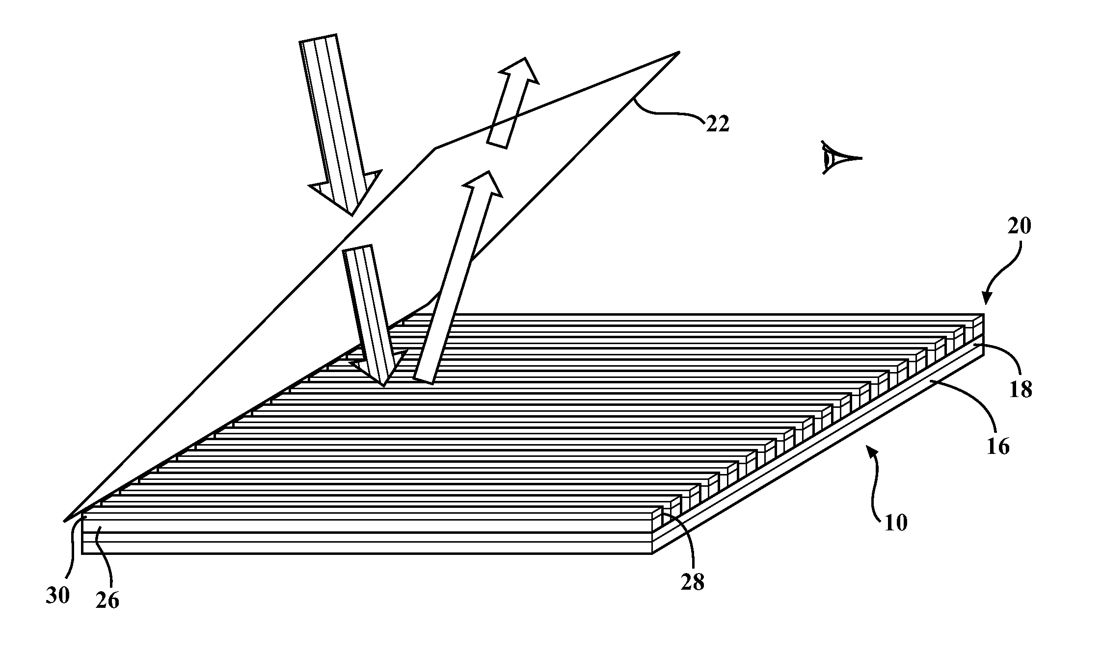
[0028]The embodiments described herein generally relate to a brightly colored panel having a WGP so as to reduce veiling glare yet maintain the bright color of the panel. The embodiments described herein also generally relate to a WGP configured to reflect P-polarized light within a predetermined spectrum and absorb all S-polarized light so as to reduce the veiling glare seen on an adjacent reflective surface, yet maintain the color of a brightly colored panel.

[0029]The brightly colored panel may be a dashboard disposed adjacent a windshield and positioned so as to receive light through the windshield. The panel further includes a substrate. The substrate may be colored brightly. The panel may further include an absorption layer mounted on the substrate. The WGP is mounted on the absorption layer.

[0030]The WGP includes a plurality of gratings formed of a metallic element. Each grating is spaced apart from the other so as to form a plurality of wave guides. The waveguides have a long...


PUM


Abstract

A wire-grip polarizer (“WGP”), and a panel having said WGP is provided. The WGP is mounted on an absorption layer. The absorption layer is mounted on a substrate. The substrate is brightly colored. The WGP includes a plurality of gratings formed of a metallic element. Each of the gratings is spaced apart from the other so as to form a waveguide. The WGP is configured to transmit S-Polarized light and reflect P-polarized light. The A thin film layer may be disposed on each of the metallic gratings. The thin film layer is configured to generate a resonance so as to modify the reflectivity of P-polarized light so as to reduce veiling glare and maintain the brightness of the substrate.

Description

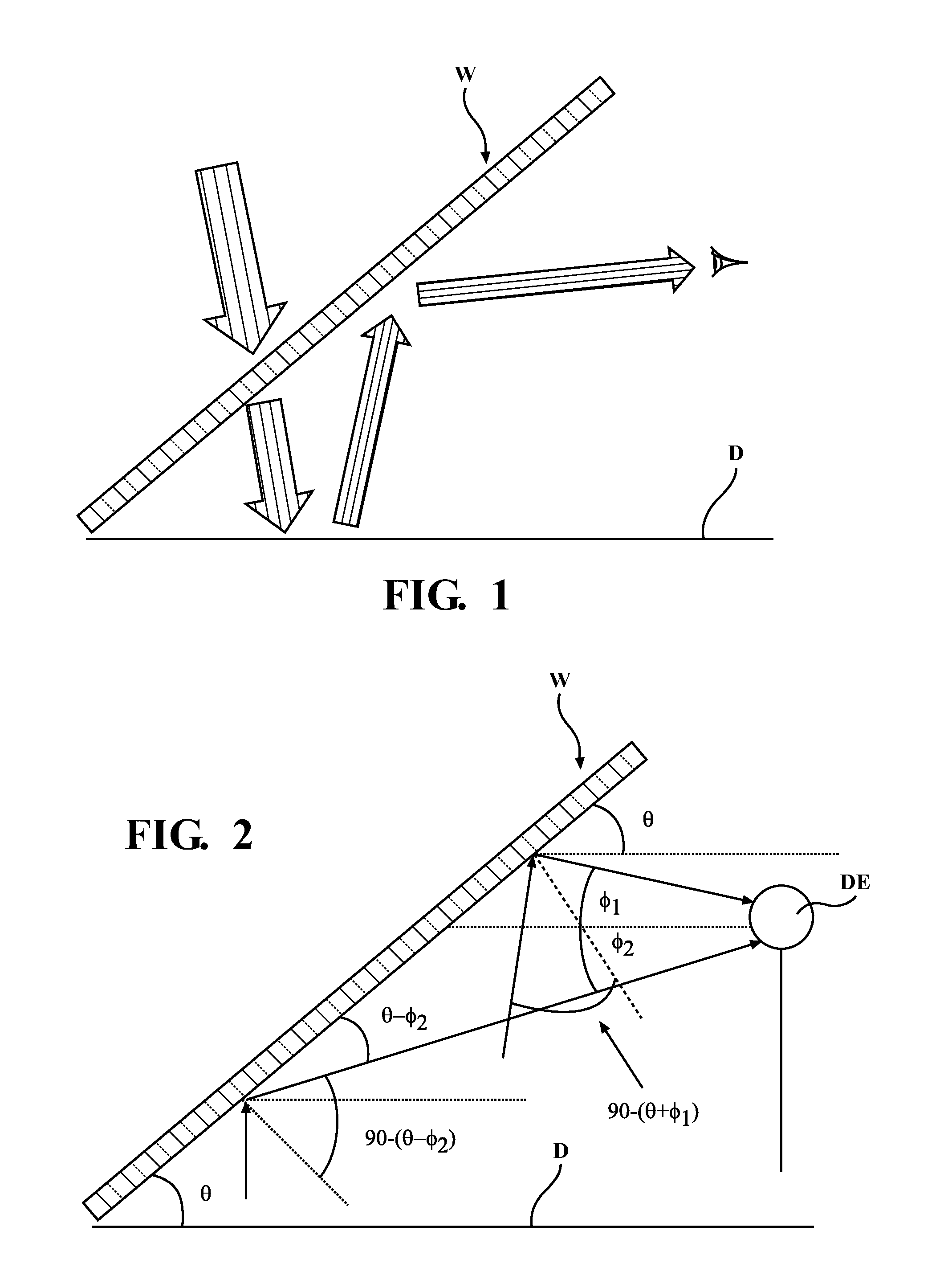
TECHNICAL FIELD[0001]A colored panel having a wire-grid polarizer configured to reduce veiling glare and maintain the brightness of the panel and a wire-grid polarizer is provided.BACKGROUND OF THE INVENTION[0002]Veiling glare are mirror-like images of an object projected onto a window. The mirror-like image is caused when light is transmitted through a window onto the object. The light reflects off the object onto the inner surface of the window.[0003]Veiling glare is a phenomenon which is commonly observed inside an automotive vehicle. In particular, light penetrates the windshield and strikes the dashboard, the dashboard (“D”) reflects the light onto the interior surface of the windshield (“W’) as depicted in FIG. 1. Thus, what is superimposed onto the windshield is a mirror image of the dashboard. The mirror image of the dashboard imposed on the windshield can lower the contrast of road scene.[0004]With reference now to FIG. 2, a perspective view showing the relationship between...

Claims


Application Information

Patent Timeline
Patent Type & Authority Applications(United States)
IPC IPC(8): G02B5/30G02B5/28
CPCG02B5/285G02B5/3058
Inventor BANERJEE, DEBASISHGUO, LINGJIE, JAYLEE, KYU-TAE
Owner RGT UNIV OF MICHIGAN
Learn More