Compactor system and method

a compactor and system technology, applied in the field of compactor systems and methods, can solve the problems of increased manufacturing costs of the compactor, difficult manipulation and transportation of the compactor's ramps, equipment and personnel injury, etc., and achieve the effect of cost-effective and safer compactors

Inactive Publication Date: 2016-03-31
TECH OIL PROD
View PDF1 Cites 0 Cited by
  • Summary
  • Abstract
  • Description
  • Claims
  • Application Information

AI Technical Summary

Benefits of technology

[0046]One of the novel features of the present invention is the establishment of the compaction force-distribution loop among the moveable upper frame portion and the plurality of side members and bottom member of the cart. The compaction force-distribution loop is accomplished by providing a frame assembly that is divided into two portions; a moveable upper frame portion and a lower fixed frame portion. Because the compacting assembly is operatively connected to the moveable upper frame portion of the frame assembly, the moveable upper frame portion will move upwards when the ram member of the compacting assembly encounters waste material in the interior of the container during compaction operations. When the moveable upper frame portion moves a required distance, the shoulder of the moveable upper frame portion engages the lip extending on the upper rim of the cart. This engagement establishes the compaction force-distribution loop and further serves to prevent the transport means affixed to the bottom member of the cart from being subjected to the compaction force, which is transferred to the moveable upper frame portion through the engagement of the lip member with the shoulder.
[0047]Because of the unique compaction force-distribution loop arrangement of the compactor system of the present invention, the compacting unit or frame assembly does not require bottom and side members to absorb the compaction force. The bottom and side members are now present on the cart, which is included within the compaction force-distribution loop, together with the moveable upper frame portion of the compacting unit. The elimination of the bottom and side members from the compacting unit achieves advantages in manufacturing as the compactor system is made more cost-effective. An estimated 75% less stainless steel is required to construct the compactor system of the present invention. The elimination also provides for a safer compactor system as the need for loading / unloading ramps to gain access to the upper surface of the bottom member, as in conventional systems, is not required. In the compactor system of the present invention, the floor structure serves as the support for the cart when place into the compacting position within the compactor unit.

Problems solved by technology

The steel forming the compacting unit's bottom and side members contribute to an increase in the manufacturing costs associated with the compactors.
This design is problematic because the weight of the carts makes their manipulation and transportation into and out of the compacting unit vis-a-vis the ramp(s) difficult particularly given the swaying-action (pitch and roll) of the marine vessel.
Because of their weight and instability on the ramps, the containers are subject to unintended movement and downward rolls off the ramp(s) that may cause injury to equipment and personnel.

Method used


Image

  • Compactor system and method
  • Compactor system and method
  • Compactor system and method

Examples


Embodiment Construction

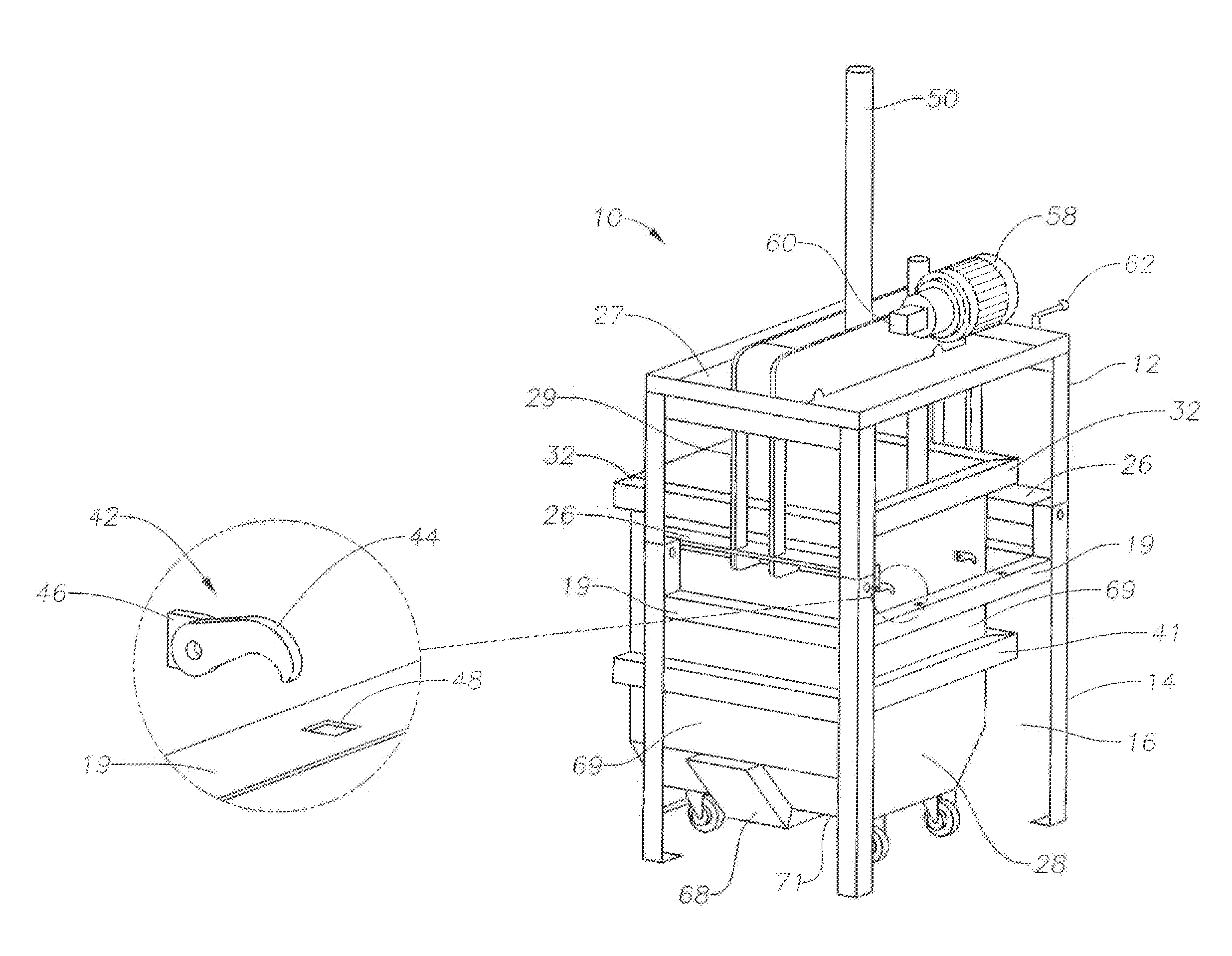
[0059]A compactor system may include a compacting unit having frame assembly 10 as shown in FIGS. 3 and 4. Frame assembly 10 may include moveable upper frame portion 12 and lower fixed frame portion 14. Frame assembly 10 may also include cavity 16. Lower fixed frame portion 14 may include support legs 18 interconnected in spaced-relation by braces 19. Support legs 18 may be configured in a square, rectangular, or other arrangement to form cavity 16. Lower fixed frame portion 14 supports moveable upper frame portion 12. Foot members 20 may be operatively connected to a lower end of each of support legs 18. Foot members 20 may be used to secure frame assembly 10 to a floor structure to stabilize the compactor system when the ship is in motion. The floor structure may be the floor of a marine vessel such as ship or offshore installation.

[0060]An upper end of each support leg 18 of lower frame portion 14 may include pin 22 and support surface 23. Upper frame portion 12 may include verti...


PUM


Abstract

A compactor system for use on board marine vessels and offshore installation. The compactor has a cart with bottom and side members capable of withstanding a compaction force. The upper rim of the cart has a lip. The system has a compaction unit formed of a movable upper frame with a shoulder and a lower fixed frame. During waste compaction, the moveable upper frame moves in an upward direction to a point where the shoulder engages the cart's lip to establish a force-distribution loop among the upper frame and the side and bottom members of the cart. The cart's wheels are not subjected to the compaction force.

Description

CROSS-REFERENCE TO RELATED APPLICATIONS[0001]This application claims the benefit of and priority to U.S. Provisional Application No. 61 / 882,952, filed Sep. 26, 2013, which is incorporated herein by reference.FIELD OF THE INVENTION[0002]The present invention relates to a compactor system and method, and more particularly, to a waste compactor system and method for use on marine vessels such as ships and offshore installations.BACKGROUND OF THE INVENTION[0003]Environmental concerns for the world's navigable waterways has led to regulations governing waste handling and disposal on marine vessels such as ships and offshore installations. The regulations have changed substantially over the past few years and continue to change to provide stricter rules for waste disposal for vessels at sea. International regulations include ISO 14001, IMO Marpol 73 / 78 Annex V and others. In the United States, the regulations include the MPRSA Marine Protection Research and Sanctuaries Act, 30 CFR Part 25...

Claims


Application Information

Patent Timeline
Patent Type & Authority Applications(United States)
IPC IPC(8): B30B9/30
CPCB30B9/3075B30B9/3042B30B9/3032B30B9/3057
Inventor ZIMMER, JOHN, C.
Owner TECH OIL PROD
Why Eureka
Try Eureka