Non pwm digital dc-dc converter

a converter and digital converter technology, applied in the direction of efficient power electronics conversion, electric variable regulation, instruments, etc., can solve problems such as unavoidable switching losses, and achieve the effect of minimizing switching losses

Inactive Publication Date: 2016-03-31
IDT EURO GMBH
View PDF7 Cites 6 Cited by
  • Summary
  • Abstract
  • Description
  • Claims
  • Application Information

AI Technical Summary

Benefits of technology

[0005]The present invention relates to switched power converter comprising a power stage for generating an output voltage according to a switching signal and an input voltage by means of a switching element. The switching signal is generated by a variable timing generator which is controlled by a compensator. The pulses of the switching signal are generated on a “need to have basis”. Hence, theses pulses may be generated independently of a PWM period. The pulses can be generated such that switching losses are minimized. A switching pattern can be matched to the load current pattern. Thus, the behavior of the compensator can be synchronized to a regular pattern of the load current. A high resolution variable timing generator may be employed.

Problems solved by technology

However, when a load current exhibits a regular pattern, PWM based control may lead to avoidable switching losses.

Method used


Image

  • Non pwm digital dc-dc converter
  • Non pwm digital dc-dc converter
  • Non pwm digital dc-dc converter

Examples


Embodiment Construction

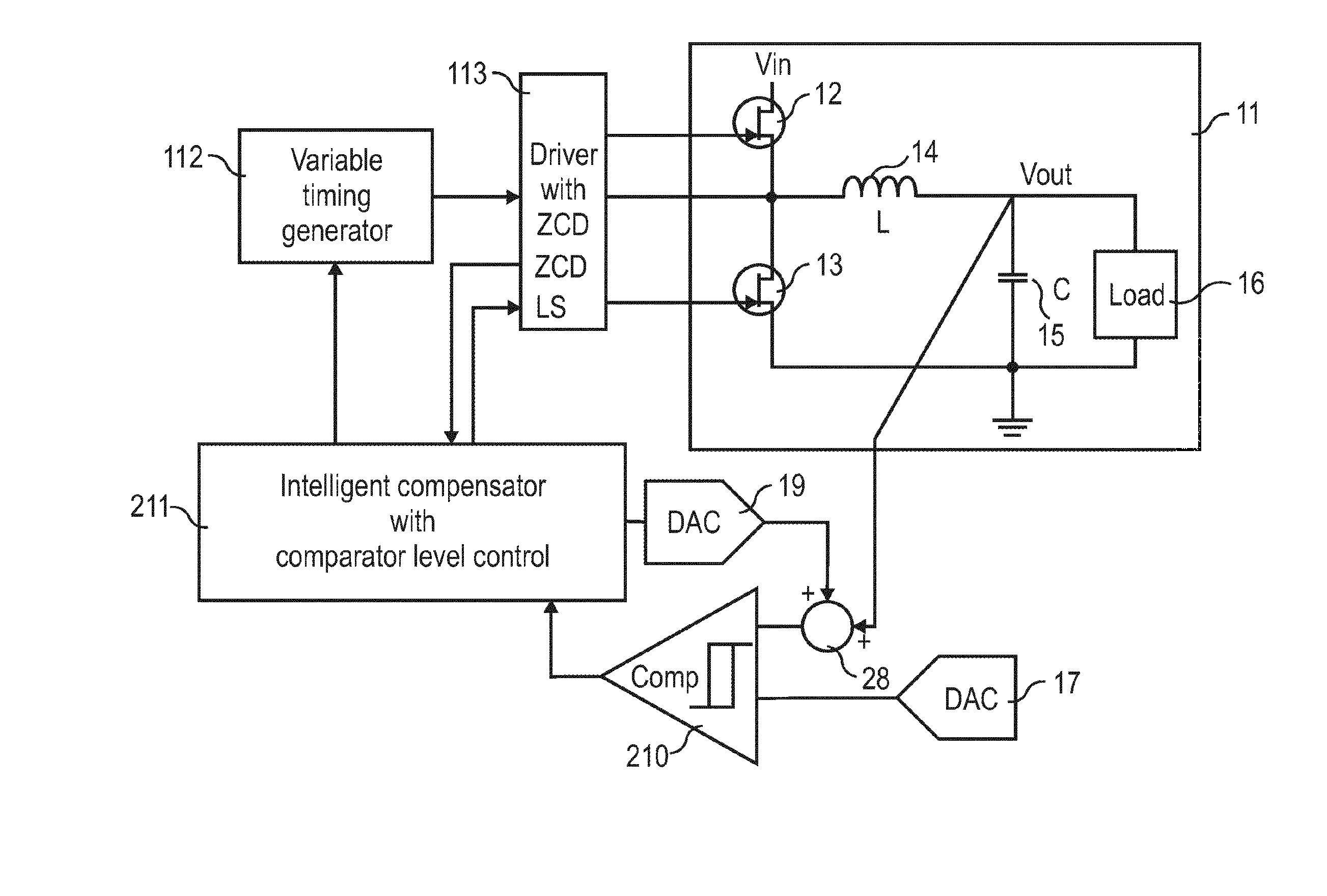
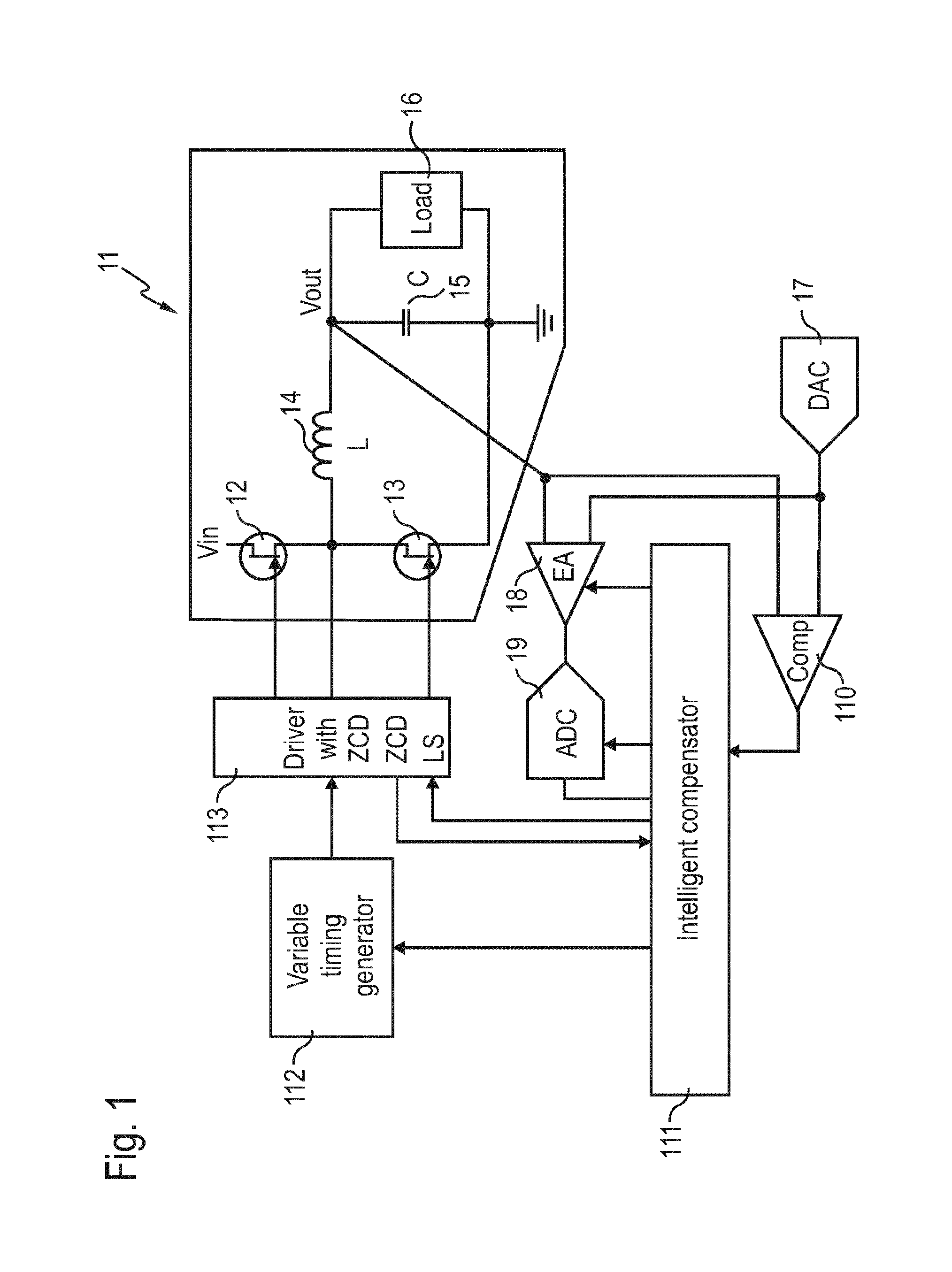
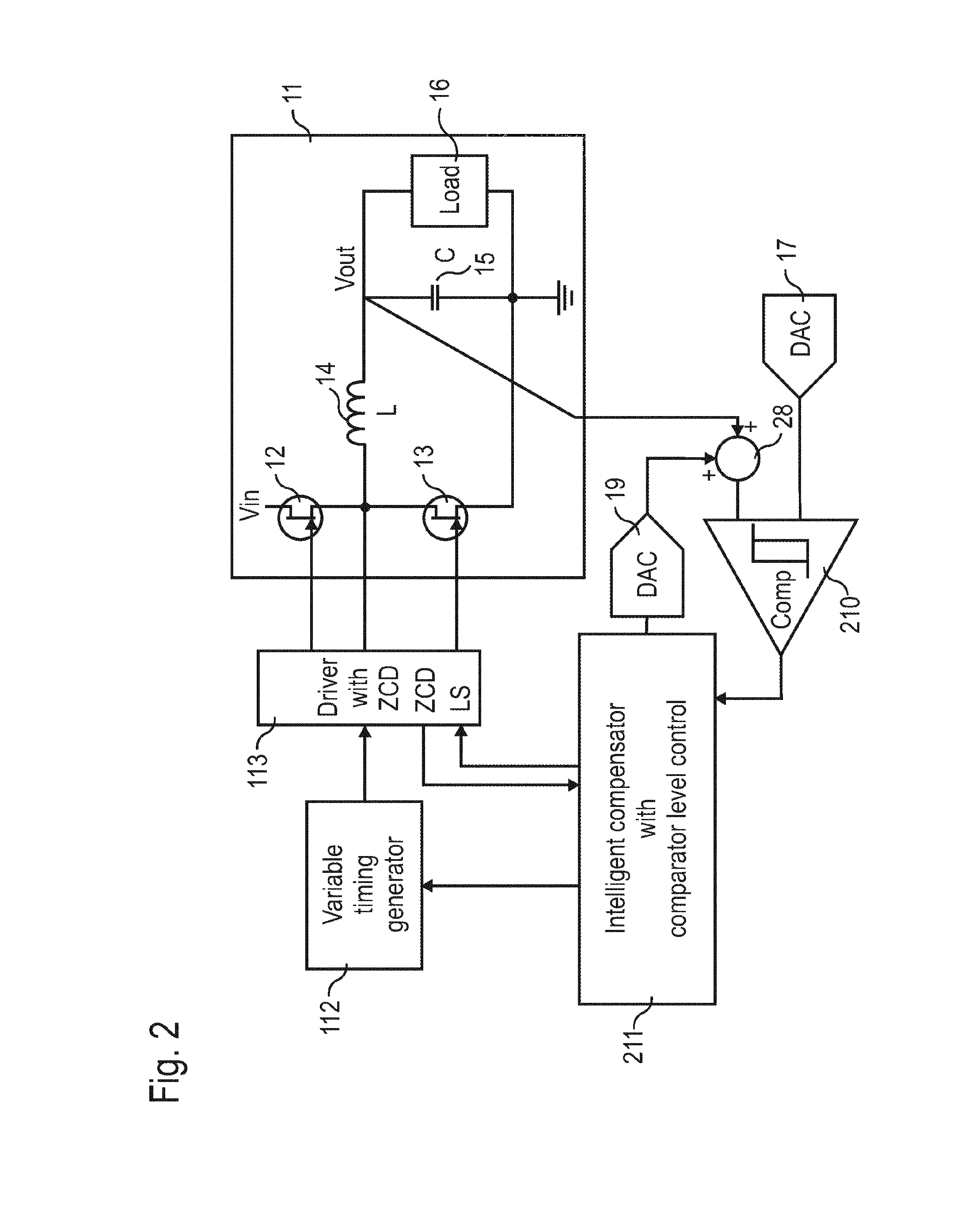
[0010]FIG. 1 shows a power converter comprising a power stage 11. The power stage 11 comprises a first switching element 12 and a second switching element 13, an inductance 14, a capacitor 15 and a load 16. The switching elements 2 and 3 are driven by a driver 113 with zero current detection. The driver 113 forwards a switching signal generated by variable timing generator 112 that is controlled by an intelligent compensator 111 on a non-PWM basis. The intelligent compensator 111 compensator controls the variable timing generator such that pulses of the switching signal are generated on a need to have basis. For this purpose, the intelligent compensator processes an error signal generated by error amplifier 18 and being digitized by ADC 19. Error amplifier 18 and ADC can be adjusted by the intelligent compensator 111. The error signal is the difference between the output voltage of the power stage 11 and a reference voltage converted to the analog domain by DAC 17. Furthermore, the ...


PUM


Abstract

A switched power converter includes a power stage for generating an output voltage according to a switching signal and an input voltage via a switching element. The switching signal is generated by a variable timing generator which is controlled by a compensator. The pulses of the switching signal are generated on a “need to have basis”. Hence, theses pulses may be generated independently of a PWM period. The pulses can be generated such that switching losses are minimized. A switching pattern can be matched to the load current pattern. Thus, the behavior of the compensator can be synchronized to a regular pattern of the load current. A high resolution variable timing generator may be employed.

Description

FIELD OF THE INVENTION[0001]The present disclosure relates to a switched power converter controlled on a none pulse width modulation (PWM) basis and related method.BACKGROUND OF THE INVENTION[0002]Switched DC-DC converters comprise a switchable power stage, wherein an output voltage is generated according to a switching signal and an input voltage. The switching signal is generated in a digital control circuit that adjusts the output voltage to a reference voltage. The switched power stage comprises a dual switch consisting of a high-side field effect transistor (FET) and a low-side FET, an inductance and a capacitor. During a charge phase, the high-side FET is turned on by the switching signal to charge the capacitor. During a discharge phase the high-side FET is turned off to drain the capacitor. The switching signal is generated as digital pulse width modulation signal with a duty cycle determined by a control law. The control law may be implemented by a PID compensator generatin...

Claims


Application Information

Patent Timeline
Patent Type & Authority Applications(United States)
IPC IPC(8): H02M3/158H02M1/00
CPCH02M3/158H02M1/0035Y02B70/10
Inventor SCHMITZ, RICHARD, MARIAMARSCHALKOWSKI, ERICYOUNG, CHRIS
Owner IDT EURO GMBH
Why Eureka
Try Eureka